Volume 24 article 1356 pages: 594-603
Received: Apr 12, 2026 Accepted: Aug 15, 2026 Available Online: Aug 16, 2026 Published: Aug 17, 2026
DOI: 10.5937/jaes0-68030
A MODEL-BASED KINEMATIC LAYER FOR DIGITAL-TWIN-ASSISTED MOTION COORDINATION OF A FORESTRY HYDRAULIC MANIPULATOR
Abstract
Modern forestry machines are complex cyber-physical and human-machine systems (HMS), in which operational efficiency is determined not only by the machine's technical characteristics but also by the quality of the operator's interaction with the working equipment. One of the most labor-intensive operations is positioning the cutting-gripping device (CGD) toward a tree, which requires coordinated control of the hydraulic manipulator's links.
The aim of this study is to develop a model-based kinematic layer for digital-twin-assisted motion coordination of a forestry hydraulic manipulator during CGD positioning toward a tree.
This paper examines an inverse kinematics problem in which the specified translational motion of the CGD determines the required displacements, velocities, and accelerations of the manipulator's links and hydraulic cylinder piston rods.
The simulation results showed that the hydraulic cylinder rod velocities vary nearly linearly, creating the prerequisites for model-based coordination of their motion. Furthermore, increasing the CGD velocity and reaching a maximum reach are accompanied by increased acceleration of the arm cylinder, which can be considered an indicator of a dynamically unfavorable operating mode.
The proposed architecture includes a geometric module, an inverse kinematics unit, a velocity and acceleration calculation module, a module for determining hydraulic cylinder motion parameters, and a block for detecting unfavorable operating modes during CGD positioning. The model is positioned as a kinematic layer and computational core of a digital-twin-assisted operator support system rather than as a complete hydraulic digital twin. The obtained results support a model-based approach to CGD motion coordination in forestry manipulators and are consistent with the implementation of Industry 4.0 technologies in forestry machines and human-machine systems.
Highlights
- Developed a model-based kinematic layer linking CGD trajectory to hydraulic cylinder rod motion.
- Inverse kinematics computes displacements, velocities and accelerations of manipulator links and cylinders.
- Hydraulic cylinder rod velocities vary nearly linearly, enabling simple motion coordination.
- Rising arm-cylinder acceleration near maximum reach flags unfavorable, dynamically risky operating modes
Keywords
Content
1 Introduction
In the context of Industry 4.0, modern forestry machines are increasingly viewed as cyber-physical systems, incorporating digital twins, intelligent control algorithms, and operator support tools [1, 2].
The diversity of technological operations performed by a forestry machine determines the requirements for precision, safety, and reliability of the entire machine-technological system [3].
Under these conditions, a typical forestry machine can be considered a human-machine system (HMS) or a human-in-the-loop system, where efficiency is determined not only by the machine's technical characteristics but also by the operator's ability to maintain stable control under dynamically changing conditions [4]. The operator not only performs direct control but also continuously evaluates the current state of the system. Furthermore, depending on the type of technological operation, the role of the human operator and the degree of their influence on the final result can vary significantly [5].
One of the most labor-intensive operations from an operator's perspective is the positioning of the cutting-gripping device (CGD), which corresponds functionally to a felling head, toward a tree [6]. At this stage, the operator controls several degrees of freedom of the hydraulic manipulator, which has its own inertia, and must ensure coordination of the various manipulator components and the accuracy of the movement trajectory. Even minor control errors can lead to increased cycle times, increased dynamic loads on the manipulator components, decreased positioning accuracy, and additional workload for the operator [7].
The human factor problem can be partially addressed through preliminary selection and professional training of operators [8], organizational measures and condition monitoring [9, 10], and improved control ergonomics [11]. However, such approaches do not eliminate the need for the operator to make quick decisions in a dynamically changing work environment.
Therefore, a promising direction is to transfer some of the functions of analyzing, predicting, and coordinating movements to intelligent technical means of operator support, including digital twins, model-based control algorithms, and systems for preventing unfavorable operating conditions. Under these conditions, the development of automated and intelligent operator assistance systems is becoming an important area for improving the efficiency and safety of forestry machines. Such support reduces sensory and cognitive load, lowers operator stress, shortens the time required to complete a process operation, and reduces the number and cost of control errors.
The practical relevance of such operator-support logic is also confirmed by studies of boom-tip control in forestry cranes. Manner et al. [12] showed that direct control of boom-tip motion can simplify crane operation for beginner-level operators compared with conventional control of separate boom movements. Recent pilot evidence also indicates that boom-tip control and related assistance technologies can improve the efficiency of forwarder loading operations [13].
A promising tool for such support is digital twins of technical systems [14]. In engineering applications, a digital twin can be used not only for simulation modeling but also as a computational core for predicting object behavior, analyzing movement patterns, identifying potentially unfavorable conditions, and generating control recommendations.
For a hydraulic manipulator of a forestry machine, digital-twin approaches can be developed at different modeling levels, including structural, dynamic, and kinematic representations [15]. In this study, this idea is developed not as a complete hydraulic digital twin, but at the level of a model-based kinematic layer, which is considered as a computational core for digital-twin-assisted motion coordination and operator support.
Existing kinematic models of manipulators are typically used to calculate the positions, velocities, and accelerations of individual points within the mechanism or to design elements of the working equipment. However, their use as a basis for intelligent motion coordination of hydraulic cylinders and operator support during CGD positioning remains insufficiently developed. In contrast to studies focused mainly on estimating the time of felling-head or CGD positioning [6], and in contrast to works considering digital-twin approaches in forestry structural mechanics [15], the present study focuses on the connection between a specified CGD trajectory, the required motion parameters of hydraulic cylinder rods, and the operator support function.
The novelty of the proposed approach lies in interpreting the inverse kinematic model not only as a calculation tool for manipulator geometry, but also as a model-based kinematic layer that can be integrated into a digital-twin-assisted operator support loop. This layer links the desired CGD trajectory with coordinated hydraulic-cylinder motion parameters and with indicators of potentially unfavorable motion modes.
The aim of this work is to develop a model-based kinematic layer for digital-twin-assisted motion coordination of a forestry manipulator and to justify its use for operator support during CGD positioning toward a tree.
To achieve this goal, the work solves the inverse kinematics problem of an articulated manipulator, in which the specified translational motion of the CGD determines the required displacements, velocities, and accelerations of the mechanism links and hydraulic cylinder rods. Based on the obtained kinematic dependencies, the motion modes of the working element at different positioning velocities are analyzed, and the structure of a model-based operator support loop is formed, in which the kinematic model is used as the computational core of a digital-twin-assisted support system.
2 Materials and methods
2.1 Statement of the problem and the concept of a model-based kinematic layer
CGD positioning toward a tree is one of the key stages of the feller buncher's operating cycle. During this operation, the operator must ensure that the tool moves toward the tree trunk along the desired trajectory while maintaining stability, positioning accuracy, and an acceptable level of dynamic loads on the manipulator components.
Generally, the hydraulic manipulator of a feller buncher is an articulated system whose movement is determined by the combined action of several links and hydraulic cylinders. During manual operation, the operator controls the hydraulic drive, and the desired trajectory of the CGD is determined by the coordinated movement of the boom, arm, and tool. This control scheme requires the operator to constantly assess the position of the CGD, its speed of approach to the tree, and the movement of the individual manipulator links.
This paper examines the problem of ensuring CGD motion close to translational motion in the direction of a tree. This formulation allows us to move from a direct analysis of the motion of individual manipulator links to an inverse kinematics problem, in which the specified motion of the end-effector determines the required displacements, velocities, and accelerations of the mechanism links and hydraulic cylinder rods. In other words, the initial condition is not the control action on individual hydraulic cylinders, but the desired trajectory of the CGD.
From an engineering perspective, this formulation has significant practical implications. If the corresponding motion parameters of the hydraulic cylinders are known for a given trajectory of the CGD, then model-based coordination of their operation becomes possible. In this case, the operator does not need to completely manually generate the motion of each manipulator link: part of the coordination function can be transferred to a computational module.
In the proposed approach, the kinematic model of the manipulator is considered as a model-based kinematic layer of a digital-twin-assisted operator support system. This layer provides a geometric and kinematic description of the working equipment and is intended to calculate and predict motion parameters during CGD positioning. Its primary function is to establish a relationship between the required movement of the CGD and the movement parameters of the manipulator links and hydraulic cylinder rods.
The problem statement is limited to the kinematic level. The model does not directly describe pressure transients, valve dynamics, oil compressibility, friction, leakage, structural flexibility, or cutting resistance. Therefore, the obtained results should be interpreted as kinematic outputs that can support motion coordination and operator assistance, rather than as a complete description of the hydraulic drive dynamics.
Conceptually, the model-based kinematic layer includes the following components: a geometric model of the articulated manipulator; an inverse kinematics calculation module; a module for determining the velocities and accelerations of links; a module for calculating the kinematic characteristics of hydraulic cylinders; a module for identifying potentially unfavorable motion modes; and an interface for generating recommendations or corrective actions for the operator support system.
The input data for such a layer are the available geometric parameters of the manipulator, the current position of the links, and the required direction and velocity of CGD movement. The output data are the required movements, velocities, and accelerations of the mechanism links, as well as the velocities and accelerations of the hydraulic cylinder rods. Based on these data, the coordination of the hydraulic drives can be assessed, trajectory sections with increased accelerations can be identified, and recommendations can be generated for the operator or control system.
Thus, the problem being solved consists of developing a kinematic model that, based on the given translational movement of the CGD, makes it possible to determine the motion parameters of the manipulator links and hydraulic cylinders, as well as to justify the use of this model as a kinematic layer for digital-twin-assisted motion coordination and operator support.
2.2 Kinematic model of the hydraulic manipulator
The modeling object is a hydraulic manipulator of a feller buncher, including a boom, an arm, a CGD, and hydraulic cylinders driving the main links. The manipulator is represented as a planar articulated mechanism, whose motion is considered in the vertical plane of CGD positioning toward the tree. This setup corresponds to the most significant stage of the technological operation, when the CGD must be moved toward the trunk along a trajectory close to translational motion.
The kinematic diagram of the manipulator is defined by a system of characteristic points corresponding to the link hinges, hydraulic cylinder attachment points, and the position of the working element (Fig. 1).
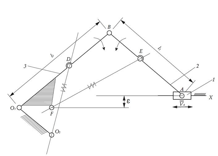
Fig. 1. Kinematic diagram of an articulated forestry manipulator
Point A corresponds to the position of the CGD. Unlike the direct problem, where the motion of the working element is determined by the specified displacements of the links, this study uses an inverse formulation: the required motion of point A is specified in advance, and the motion parameters of the links and hydraulic cylinders are determined based on the kinematic relationships of the mechanism.
The numerical model was developed for the LP-19 forestry feller-buncher. The available technical and design parameters used in the simulation are summarized in Table 1. The complete manufacturer coordinate model of all joint centers and hydraulic cylinder attachment points was not available in the source data used in this study. Therefore, the simulation should be interpreted as an idealized kinematic reconstruction based on the equivalent kinematic scheme and available LP-19 technical data.
Table 1. Available LP-19 parameters used in the simulation
|
Parameter |
Value |
Comment |
|
Machine type |
LP-19 |
Forestry feller-buncher |
|
CGD displacement range |
3.8–8.0 m |
Minimum–maximum reach |
|
Boom cylinder parameters |
140 × 90 × 1120 mm |
Bore × rod × stroke |
|
Arm cylinder parameters |
140 × 90 × 1400 mm |
Bore × rod × stroke |
|
CGD stand cylinder parameters |
140 × 90 × 1400 mm |
Bore × rod × stroke |
|
Representative CGD velocity, mode 1 |
0.39 m/s |
Without diverter |
|
Representative CGD velocity, mode 2 |
0.67 m/s |
With diverter |
|
Operation time, mode 1 |
13.2 s |
Movement from 3.8 to 8.0 m |
|
Operation time, mode 2 |
7.7 s |
Movement from 3.8 to 8.0 m |
|
Numerical tool |
Microsoft Excel 2010 |
Spreadsheet procedure |
The calculations were performed using a custom spreadsheet-based numerical procedure. The CGD displacement interval from 3.8 to 8.0 m was considered as the main positioning range. For each characteristic position of the CGD, the inverse kinematics problem was solved, after which the positions of the manipulator links, hydraulic cylinder lengths, rod velocities, and acceleration-related parameters were determined. Since the calculation was position-based and kinematic rather than a time-marching hydraulic dynamic simulation, no dynamic solver settings such as pressure solver tolerances or hydraulic time-step parameters were used.
The main condition of the modeling is the translational motion of the CGD toward the tree at a specified velocity VA. For each position of the manipulator, the velocities and accelerations of the characteristic points of the mechanism, as well as the angular velocities and angular accelerations of the links, are determined. The vector relationships of the velocities are written based on the velocity addition theorem for planar motion of the links:
where $\vec{V}_B$ is the velocity of the hinge point B; $\vec{V}_A$ is the specified velocity of the CGD; $\vec{V}_BA$ is the relative velocity of point B with respect to point A; $\vec{V}_O1$ is the velocity of point O1; $\vec{V}_BO1$ is the relative velocity of point B with respect to point O1.
Vector $\vec{V}_BO1$ is directed perpendicular to link O1B, and its magnitude is determined by the angular velocity of the corresponding link and the distance from point O1 to point B. The directions of the relative velocities $\vec{V}_BA$ and $\vec{V}_BO1$ are determined by the condition of their perpendicularity to the corresponding links BA and BO1, which reflects the tangential nature of the relative motion of the link points during planar rotation.
Based on the obtained velocities, the angular velocities of the corresponding links are determined:
where $\omega_i$ is the angular velocity of the i-th link; $V_i$ is the linear velocity of the characteristic point or the relative velocity of the link point; $\ell_i$ is the length of the corresponding link or arm of the mechanism.
To analyze dynamically significant modes, the accelerations of characteristic points are additionally determined. Generally, the acceleration of a link point is represented as the sum of the translational, relative, normal, and tangential components.
For manipulator links, normal acceleration is defined by the expression:
Tangential components of accelerations are used to determine the angular accelerations of links:
where $a_i^\tau$ is the tangential component of acceleration.
The general kinematic formulation allows two characteristic motion cases to be distinguished: a transient acceleration/deceleration phase, in which VA ≠ const, and a steady-state positioning phase, in which VA = const. In the present study, the numerical simulation focuses on the steady-state positioning phase with constant representative CGD velocities of 0.39 and 0.67 m/s. The transient acceleration and deceleration phases are considered only conceptually and are not parameterized by a separate velocity-time law in this paper.
A separate modeling step is devoted to determining the kinematic characteristics of the hydraulic cylinders. For this purpose, the attachment points of the boom and arm cylinders are included in the kinematic diagram. The motion of each hydraulic cylinder is considered as a combination of the rotational motion of the cylinder body relative to the pivot point and the translational motion of the piston rod.
The velocity of the hydraulic cylinder rod is determined by the change in its current length over time:
where $V_{cyl}$ is the rod velocity, and $L_{cyl}$ is the current cylinder length, defined as the distance between its hinge attachment points.
The acceleration of the rod is defined as the derivative of the rod velocity with respect to time:
When determining the acceleration of hydraulic cylinders, it is considered that their motion includes both a translational component associated with the piston rod's movement and a rotational component caused by changes in the position of the hydraulic cylinder body relative to the pivot points. Therefore, the acceleration calculation additionally takes into account the Coriolis component, which arises from the relative movement of the piston rod within the rotating link.
Although the proposed model is kinematic and does not describe nonlinear hydraulic dynamics, its outputs can be interpreted in terms of basic hydraulic drive requirements. For a hydraulic cylinder with effective piston area Ai, the rod velocity obtained from the kinematic model determines the required volumetric flow rate:
where $Q_i$ is the required flow rate of the i-th hydraulic cylinder, $A_i$ is the effective piston area, and $V_{cyl,i}$ is the rod velocity.
If the pressure in the cylinder chamber is known, the corresponding ideal actuator force can be estimated as:
where $p_i$ is the hydraulic pressure.
These relationships do not replace a hydraulic dynamic model with valve nonlinearities, friction, leakage, fluid compressibility, pressure losses, and control delays. However, they provide an engineering interpretation of the kinematic outputs and show how the proposed kinematic layer can be connected to a hydraulic control system in a digital-twin-assisted operator support framework.
As a result, the kinematic model allows the following parameters to be determined for a given CGD motion: the positions of the manipulator links; the velocities and accelerations of characteristic points; the angular velocities and angular accelerations of the links; and the displacements, velocities, and accelerations of the hydraulic cylinder rods. These parameters form the computational basis of the model-based kinematic layer.
In terms of subsequent motion coordination, the most important result of the model is establishing a relationship between the required CGD trajectory and the operating parameters of the hydraulic cylinders. If the specified CGD motion is close to translational, the model makes it possible to determine the hydraulic cylinder rod motion modes that ensure coordinated movement of the boom and arm. This creates the prerequisites for using the model as part of a digital-twin-assisted operator support system, where the kinematic layer performs calculation, prediction, and detection of potentially unfavorable motion modes.
2.3 Architecture of the model-based kinematic layer and intelligent motion coordination
The developed kinematic model can be used not only to calculate the manipulator motion parameters but also as the computational core of a model-based kinematic layer within a digital-twin-assisted operator support system.
In this paper, the model-based kinematic layer is defined as a geometric and kinematic representation of the working equipment that allows the specified CGD motion to be related to the required displacements, velocities, and accelerations of the manipulator links and hydraulic cylinder rods.
At this level, the proposed layer is aimed at supporting CGD positioning toward a tree by calculating and predicting motion parameters of the manipulator links and hydraulic cylinder rods. Its function is limited to the geometric and kinematic level, while hydraulic dynamics, pressure transients, valve characteristics, and control delays are considered outside the scope of this model. This setup allows the kinematic model to be used as a computational module for digital-twin-assisted motion coordination and subsequent operator assistance (Fig. 2).
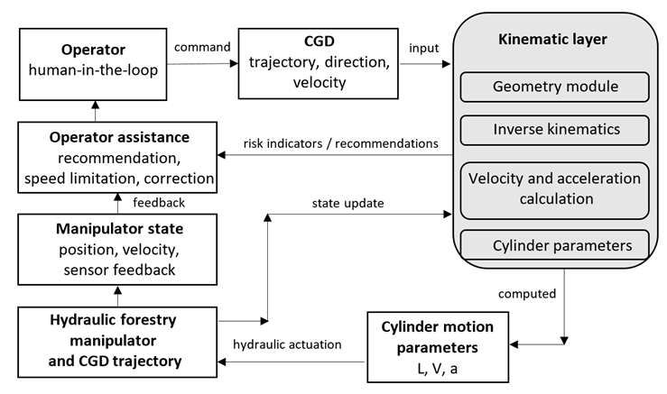
Fig. 2. Architecture of the model-based kinematic layer for digital-twin-assisted motion coordination and operator support
The architecture of the model-based kinematic layer includes several functional blocks. The first block contains a geometric description of the manipulator based on the available model parameters, including link geometry, hydraulic cylinder attachment points, and the current position of the CGD. The second block implements an inverse kinematic problem, in which the specified motion of the end-effector determines the required link motion parameters. The third block calculates the velocities and accelerations of the mechanism's characteristic points, as well as the angular velocities and angular accelerations of the links. The fourth block determines the displacements, velocities, and accelerations of the hydraulic cylinder rods. The fifth block evaluates the motion mode and identifies areas where increased accelerations and dynamic loads are possible.
The input parameters of the kinematic layer are the current position of the manipulator, the desired direction of CGD movement, the specified velocity of CGD movement, and the available geometric parameters of the mechanism. The output parameters are the required displacements of the hydraulic cylinder rods, their velocities and accelerations, and indicators of potentially unfavorable conditions. These indicators include a sharp increase in piston rod acceleration, inconsistency in hydraulic cylinder movement, reaching the manipulator's maximum reach, and the need to change the direction or velocity of the working element.
The intelligent coordination of movements in the proposed approach is based on the operator setting or initiating the desired movement of the CGD, and the kinematic layer determining the hydraulic cylinder movement parameters that must ensure this trajectory. In this case, control of the working equipment can be organized not as independent manual action on individual hydraulic cylinders, but as model-based coordination of their operation. This reduces the need for constant manual correction of the movement of multiple manipulator components.
From an operator support perspective, the kinematic layer within a digital-twin-assisted system can perform three main functions:
- computational: the system determines the required hydraulic cylinder motion parameters to ensure the specified trajectory of the working element;
- diagnostic: the system identifies conditions in which acceleration or misalignment of movements can lead to increased dynamic loads;
- advisory or corrective: the system can generate prompts for the operator, limit the movement velocity in an unfavorable zone, or transmit control actions to the automated hydraulic cylinder coordination circuit.
Thus, the model-based kinematic layer acts as an intermediary between the operator and the hydraulic manipulator within a digital-twin-assisted operator support framework. It does not replace the operator, but redistributes some of the calculation and motion coordination functions from the human to a computational module. This is especially important for operations in which the operator must simultaneously monitor the position of the CGD, the movement trajectory, the velocity of approach to the tree, and the state of the hydraulic equipment.
The proposed approach is consistent with the logic of building intelligent operator support systems for human-machine systems. In such a system, the operator retains a leading role in decision-making, while the model-based kinematic layer reduces control uncertainty, provides prediction of kinematic parameters, and allows for the early identification of modes that could lead to increased dynamic loads or positioning errors.
3 Results and discussion
To evaluate the capabilities of the proposed model-based kinematic layer, CGD positioning modes were examined at two representative forward velocities of the working element. The simulation was performed for CGD movement from the near position to the maximum reach of the manipulator. The main machine parameters, displacement range, cylinder parameters, and representative velocities used in the simulation are summarized in Table 1. Therefore, they are not repeated in this section.
The characteristic velocity values were 0.39 m/s and 0.67 m/s. The first value corresponds to CGD positioning without the use of an additional diverter in the hydraulic system, while the second corresponds to CGD positioning with a diverter installed in the hydraulic system. For the range of CGD movements considered from 3.8 to 8.0 m, the average operation time was 13.2 and 7.7 seconds, respectively. These two values were selected as representative operating modes of the LP-19 machine rather than as a complete parametric study over the full range of possible velocities. Therefore, the results should be interpreted as preliminary kinematic simulation outputs illustrating the capabilities of the proposed model-based layer.
The results obtained demonstrate that the required movements of the boom and arm cylinders are coordinated at the kinematic level and can be determined based on the specified translational motion of the CGD.
Moreover, the hydraulic cylinder motion graphs retain their general form for different positioning velocities, while the differences between modes are primarily manifested in the operation time and the values of the piston rod velocities and accelerations. This indicates the feasibility of using a single kinematic model to calculate the required cylinder rod motion parameters for the considered representative operating modes.
An analysis of the hydraulic cylinder piston rod velocities showed that, in the modes examined, they vary nearly linearly (Fig. 3).
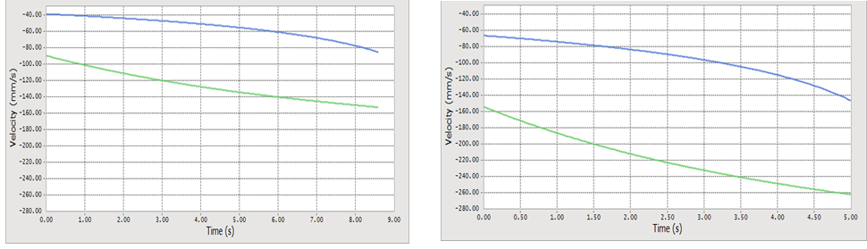
Fig. 3. Cylinder rod velocities for VA = 0.39 m/s and VA = 0.67 m/s: blue curve – arm cylinder rod; green curve – boom cylinder rod
This result has practical engineering importance, as it demonstrates the feasibility of model-based hydraulic cylinder motion coordination using a relatively simple relationship between rod velocities.
In this case, the kinematic layer can be used to pre-calculate the required piston rod velocity ratio. However, implementation of this ratio in a real hydraulic system requires further consideration of hydraulic dynamics, valve characteristics, oil compressibility, friction, leakage, and control delays. Similar issues are discussed by Zhou et al. [16] for long-stroke hydraulic manipulators, where structural deformation is considered, an important factor affecting manipulator motion during grasping and handling tasks. This supports the interpretation of the proposed model as a kinematic layer that should later be extended toward deformation-aware and dynamic modeling.
At the same time, acceleration analysis shows that increasing the CGD positioning velocity leads to an increase in the dynamic loading indicators at the kinematic level (Fig. 4,5).
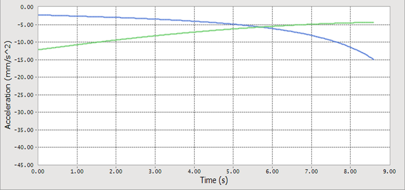
Fig. 4. Cylinder rod accelerations for VA = 0.39 m/s: blue curve – arm cylinder rod; green curve – boom cylinder rod
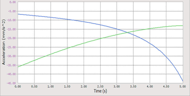
Fig. 5. Cylinder rod accelerations for VA = 0.67 m/s: blue curve – arm cylinder rod; green curve – boom cylinder rod
The most pronounced increase in acceleration is observed for the arm cylinder as the manipulator approaches its maximum reach. This means that this section of the trajectory can be considered the most critical for monitoring potential dynamic loading and supporting the operator. Within the model-based kinematic layer, such sections can be interpreted as potentially unfavorable conditions requiring velocity limitation, changes to the motion law, or the generation of a warning signal for the operator.
The obtained simulation results are also consistent with previously reported experimental findings for the LP-19 machine. In those experiments, the use of an additional electrohydraulic control element reduced the vertical deviation of the CGD trajectory and shortened the CGD positioning operation from 13.2 to 7.7 seconds. In the present paper, these data are not treated as a full experimental validation of the proposed digital-twin-assisted kinematic layer. Rather, they are used as supporting evidence that coordinated control of the boom and arm hydraulic cylinders is relevant for improving CGD positioning.
The results should also be compared with existing approaches to forestry manipulator control and CGD positioning. While some studies focus mainly on estimating the time required to point a grip-cutting device toward a tree [6], the proposed approach links the specified CGD trajectory with the required motion parameters of the hydraulic cylinder rods. Similar kinematic-control problems for forestry knuckle booms were considered by Löfgren and Wikander [17], who focused on computer-controlled boom-tip motion along a predefined path. More advanced dynamic control of hydraulic forestry cranes has been studied by Kalmari et al. [18], who applied nonlinear model predictive control to boom-tip motion and automatic sway damping. Compared with such dynamic control approaches, the present study is limited to the kinematic layer and uses it as a computational basis for cylinder-motion coordination and operator support. Compared with broader digital-twin approaches in forestry structural mechanics [15], the present study focuses on the kinematic layer as a computational core for motion coordination.
The obtained results allow us to identify two levels of practical application for the model. The first level is related to engineering design and preliminary assessment of the hydraulic system. At this level, the model allows us to determine the displacements, velocities, and accelerations of the hydraulic cylinder rods required to ensure approximately translational CGD motion toward a tree. These parameters can be used as input data for selecting hydraulic drive parameters, matching devices, and control algorithms.
The second level is associated with intelligent operator support. At this level, the model-based kinematic layer is used not only to calculate motion parameters but also to evaluate the quality of the current motion mode. If the calculated piston rod accelerations or the degree of misalignment of the hydraulic cylinders exceed permissible values, the system can generate a recommendation for the operator, limit the velocity of the working element, or transmit a corrective action to the automated coordination module. Thus, the model becomes not only a calculation tool but also an element of the operator assistance system.
From the perspective of human-machine systems, the proposed approach allows for the redistribution of some control functions between the operator and the intelligent technical module. The operator retains the leading role in target selection and process control, but the model-based kinematic layer supports the calculation of coordinated hydraulic cylinder motion and the identification of dynamically unfavorable sections of the trajectory. This reduces the need for constant manual correction of the manipulator's multiple degrees of freedom and can reduce the cognitive load during CGD positioning toward a tree.
Thus, the simulation results indicate that the proposed model can be used as a kinematic basis for digital-twin-assisted motion coordination of a forestry manipulator. The nearly linear nature of hydraulic cylinder piston rod velocity changes creates the preconditions for implementing a simple coordination law, while the identification of areas with increased acceleration allows the model to be used for detecting potentially unfavorable motion modes and supporting the operator. At the same time, the analysis is limited to two representative operating velocities and should be expanded in future work through a broader parametric study and experimental validation using measured CGD trajectories, cylinder rod displacements, and operator control actions.
4 Conclusions
This paper proposes an approach to representing the motion of a forestry manipulator using a model-based kinematic layer. This layer is intended for digital-twin-assisted motion coordination and operator support during CGD positioning toward a tree.
The contribution of this study lies in the development of a computational kinematic core that relates the specified CGD motion to the motion parameters of the manipulator links and hydraulic cylinder rods and can be integrated into an operator support system.
The developed kinematic model makes it possible to determine the motion parameters of the manipulator links and hydraulic cylinder rods based on the specified translational motion of the CGD.
The model calculates the positions, velocities, and accelerations of the mechanism's characteristic points, the angular velocities and angular accelerations of the links, as well as the displacements, velocities, and accelerations of the hydraulic cylinder rods. This establishes a relationship between the desired CGD trajectory and the coordinated motion of the boom and arm hydraulic cylinders.
The simulation results show that the hydraulic cylinder rod velocities change almost linearly in the considered modes. This creates the preconditions for implementing a relatively simple motion coordination law at the kinematic level. At the same time, acceleration analysis revealed that, as the CGD velocity increases and the manipulator approaches its maximum reach, the acceleration of the arm cylinder increases. Such trajectory sections can be considered potentially unfavorable motion modes requiring velocity limitation, motion law adjustment, or operator warning.
The two CGD velocities considered in the simulation should be interpreted as representative LP-19 operating modes rather than as a complete parametric study.
The proposed model-based kinematic layer can be used at two levels. At the engineering level, it provides initial data for preliminary assessment of hydraulic cylinder rod motion parameters, selection of hydraulic drive components, and development of motion coordination algorithms. At the human-machine system level, it can be used as an element of a digital-twin-assisted operator support system, enabling calculation of required motion parameters, identification of high-acceleration modes, and generation of recommendations or corrective actions.
The obtained results are consistent with the logic of developing intelligent systems for supporting the dynamic stability of human-machine system operators. In this case, operator support is provided not through full automation of the technological operation, but through a redistribution of functions: the operator retains the leading role in target selection and process control, while the kinematic layer performs calculation, prediction, and identification of potentially unfavorable motion modes.
A limitation of this study is that the proposed model describes only the geometric and kinematic layer of the manipulator. It does not fully account for nonlinear hydraulic drive dynamics, valve characteristics, friction, leakage, fluid compressibility, pressure losses, elastic deformations of structural elements, control system delays, external disturbances, cutting resistance, or individual operator behavior. In addition, the complete manufacturer coordinate model of all joint centers and hydraulic cylinder attachment points was not available in the source data used in this study. Therefore, the presented results should be interpreted as an idealized kinematic simulation based on the equivalent kinematic scheme and available LP-19 technical data.
Further research will focus on extending the proposed kinematic layer to a dynamic model of the hydraulic manipulator, incorporating position, pressure, and flow sensor data, and developing algorithms for online evaluation of manipulator motion modes. A separate focus will be the experimental validation of the model using measured CGD trajectories, hydraulic cylinder rod displacements, operation times, and operator control actions.
Further work should also include a broader parametric analysis of CGD positioning velocities and a formal description of transient acceleration and deceleration phases. This will enable the transition from a kinematic computational core to a more comprehensive digital-twin-assisted system for motion coordination and operator support.
Acknowledgements
These results were obtained with the support of the Russian Science Foundation Grant No. 23-19-00568-П “Methods and intelligent system for supporting dynamic stability of operators of ergatic systems”, https://rscf.ru/en/pro-ject/23-19-00568-П/
References
- Humphrey, P., Harvey, C., & Visser, R. (2024). Deploying an early-stage cyber-physical system for the implementation of Forestry 4.0 in a New Zealand timber harvesting context. iForest—Biogeosciences and Forestry, 17(6), 353. https://doi.org/10.3832/ifor4651-017
- Gaur, V., & Verma, R. (2026). Revolutionizing industries through cyber-physical systems: A systematic review. Discover Computing, 29(1), 250. https://doi.org/10.1007/s10791-026-10125-w
- Brown, M., et al. (2020). The progression of forest operations technology and innovation. Australian Forestry, 83(1), 1–3. https://doi.org/10.1080/00049158.2020.1723044
- Chernykh, D., et al. (2023). The approach to training logging machinery operators. Journal of Applied Engineering Science, 21(1), 70–75. https://doi.org/10.5937/jaes0-38214
- Petukhov, I., & Steshina, L. (2014). Assessment of vocational aptitude of man-machine systems operators. In 2014 7th International Conference on Human System Interactions (HSI). IEEE. https://doi.org/10.1109/HSI.2014.6860446
- Andronov, A. V., et al. (2021). A model for determining the time of pointing a grip-cutting device of feller buncher machines on a growing tree. Izvestia Sankt-Peterburgskoj Lesotehniceskoj Akademii, (237), 183–195. https://doi.org/10.21266/2079-4304.2021.237.183-195
- Goldenberg, A. A., et al. (2002). A remote manipulator for forestry operation. IEEE Transactions on Robotics and Automation, 11(2), 185–197. https://doi.org/10.1109/70.370501
- Steshina, L., et al. (2019). Training of high-skilled workers using exercisers and simulators. In 2019 3rd European Conference on Electrical Engineering and Computer Science (EECS). IEEE. https://doi.org/10.1109/EECS49779.2019.00036
- Häggström, C., & Lindroos, O. (2016). Human, technology, organization and environment—a human factors perspective on performance in forest harvesting. International Journal of Forest Engineering, 27(2), 67–78. https://doi.org/10.1080/14942119.2016.1170495
- Titova, L., & Sobczuk, H. (2022). Typology of means of technical control of physiological and ergonomic indicators of machines for forestry works. Machinery & Energetics, 13(1), 40–48. https://doi.org/10.31548/machenergy.13(1).2022.40-48
- Sokolov, A., Seliverstov, A., & Sukhanov, Y. (2023). Forest machine automation and ergonomics. E3S Web of Conferences, 389, 03002. https://doi.org/10.1051/e3sconf/202338903002
- Manner, J., et al. (2017). Forwarder crane’s boom tip control system and beginner-level operators. Silva Fennica, 51(2), Article 1717. https://doi.org/10.14214/sf.1717
- Hartsch, F., et al. (2024). Effects of boom-tip control and a rotating cabin on loading efficiency of a forwarder: A pilot study. Croatian Journal of Forest Engineering, 45(1), 71–84. https://doi.org/10.5552/crojfe.2024.2179
- Tagarakis, A. C., et al. (2024). Digital twins in agriculture and forestry: A review. Sensors, 24(10), 3117. https://doi.org/10.3390/s24103117
- Zarevich, A., et al. (2024). Structural mechanics in forestry based on digital twin. BIO Web of Conferences, 145, 05005. https://doi.org/10.1051/bioconf/202414505005
- Zhou, H., Zhang, X., & Liu, J. (2023). A practical method for the deformation of long-stroke hydraulic manipulators in grasping-handling tasks. Journal of Field Robotics, 40(4), 862–878. https://doi.org/10.1002/rob.22160
- Löfgren, B., & Wikander, J. (2009). Kinematic control of redundant knuckle booms. International Journal of Forest Engineering, 20(1), 22–30. https://doi.org/10.1080/14942119.2009.10702572
- Kalmari, J., Backman, J., & Visala, A. (2014). Nonlinear model predictive control of hydraulic forestry crane with automatic sway damping. Computers and Electronics in Agriculture, 109, 36–45. https://doi.org/10.1016/j.compag.2014.09.006
Conflict of Interest Statement
The authors declare that there was no conflict of interest
Author Contributions
Data Availability Statement
There is no dataset associated with the study or data is not shared
Supplementary Materials
There are no supplementary materials to include