Volume 23 number 3 article 1294 pages 575-586
Received: Apr 28, 2025 Accepted: Aug 25, 2025 Available Online: Sep 13, 2025 Published: Sep 15, 2025
DOI: 10.5937/jaes0-58487
APPLICATION OF THE FINITE ELEMENT METHOD TO INVESTIGATE THE IMPACT OF FRONTAL COLLISIONS ON THE DRIVER OF A 29-SEAT PASSENGER BUS
Abstract
Passenger buses are widely used across all countries, operating at high frequencies and speeds. This study analyzes the effects of frontal collisions on the driver of a 29-seat passenger bus, using the UN/ECE R29 regulation as the crash test condition. Additional evaluation standards were also integrated to assess the driver's injury risks during the simulation, which was conducted using the finite element method. Results indicate that in the baseline (non-improved) bus configuration, the intrusion into the driver’s cabin reached 510 mm. The impact on the driver’s right femur recorded a peak force of 2976.3 N, while the neck sustained a maximum bending moment of 53108.12 Nmm. However, after incorporating an energy-absorbing crash box, significant improvements were observed. The intrusion depth was reduced by 16.88% to 424.167 mm. The force transmitted to the right femur decreased by 31.13%, with a new peak value of 2049.6 N, and the maximum neck bending moment dropped by 14.14% to 45594.26 Nmm. These results demonstrate that the addition of an energy-absorbing beam significantly enhances the frontal crash safety performance of the 29-seat passenger bus, particularly in reducing the injury risks to the driver.
Highlights
- Finite element modeling applied to assess frontal crash effects on a 29-seat bus driver.
- Incorporating a crash box cut cabin intrusion by nearly 17%.
- Peak femur force reduced by about one-third, neck bending moment fell 14%.
- Improved bumper design shows clear benefits for driver protection under ECE R29.
Keywords
Content
1 Introduction
The situation of road traffic accidents involving 29-seat buses in Vietnam in 2024 remains alarming, particularly on expressways. In the first seven months alone, more than 14,200 accidents were recorded, resulting in over 6,200 fatalities and nearly 11,000 injuries, with buses, including 29-seat types, accounting for a considerable proportion. The WHO Global Status Report on Road Safety 2023 [1] estimated 1.19 million road traffic deaths worldwide in 2021 (15 per 100,000 people), ranking as the 12th leading cause of death and the top cause among those aged 5–29, with buses and public transport vehicles accounting for 19% of global traffic fatalities, rising to 22% in Southeast Asia.
Key research includes Holenko et al. [2], who simulated frontal impacts on low-entry buses using UN/ECE R29 standards. Results showed excessive deformation (up to 577 mm at 137 ms), indicating inadequate frontal stiffness and unsuitability of standard R29 anchoring methods for buses. They recommended structural redesign with energy-absorbing zones.
Lopes et al. [3,13] applied FEM to frontal and rollover tests on a Class III M3 bus, using ECE R29 for assessing cabin strength in truck collisions and ECE R66 for evaluating rollover structural integrity of buses. Impacts were measured using Digital Image Correlation, producing deformation-time and force-displacement curves for compliance assessment and design improvements.
In Vietnam, Luu [4] simulated full frontal impacts based on EURO NCAP standards, revealing significant deformation at the front frame and undercarriage. The study concluded that current designs lack sufficient energy absorption and require structural optimization.
Despite these efforts, studies specifically on 29-seat bus collisions and driver safety remain limited. This research addresses that gap through an FEM-based investigation of frontal collisions on a 29-seat passenger bus driver.
2 Materials and methods
2.1 Element Method (FEM)
In nonlinear finite element analysis, the equations of motion are typically formulated based on the principle of virtual work—a variational form that accounts for internal forces, contact and friction effects, inertia, damping, external loads, and boundary constraints [15,16]. Discretizing these during overning equations using the finite element method (FEM) leads to a system of second-order nonlinear differential equations expressed in matrix form as[5]:
| \[\left[M\right].\left(\ddot{X}\right)+\left[K\right]\left(X\right)=F_{ext}\] | (1) |
Where (X) is the current node position vector and ( ) is the node acceleration vector. [M] is the mass matrix. [K] is the stiffness matrix and Fext is the vector of external forces. This equation is nonlinear (in (X) and ( )) due to the presence of contacts, possible materials, and geometric nonlinearities. To solve this system effectively, a time integration method capable of handling such nonlinearities is essential.
2.2 Frontal Collision Analysis
A 29-seat passenger bus has been modeled as an impact impulse problem. During the energy transformation process that occurs in a collision [17,18,19], part of the initial kinetic energy is converted into deformation energy (including both elastic and plastic energy). The energy absorbed during a collision or the deformation energy occurring in the material is calculated using the formula[5]:
| \[U_e=\frac{1}{2}\int{\sigma.\varepsilon.dv}=\frac{1}{2}K_{eq}.\delta_{max}^2\] | (2) |
The specific energy absorption (SEA) parameter is evaluated to assess the material’s capability to absorb energy with reduced weight, aiming to achieve improved or equivalent impact performance compared to the current structure, as described by the formula:
| \[SAE=U_e/\ Mass\] | (3) |
where σ, ε and v are equal to the stress tensor; the strain tensor and the element volume respectively. Keq, an inherent property of the material, is the stiffness of the body related to the deflection (δ) and the resulting force. In elastic collisions, objects may collide with different velocities, but when they come into contact with each other, this interaction can cause them to reach the same velocity.
For inelastic collisions, objects share the same kinetic energy from the initial motion until they reach the point of maximum displacement, just before they separate.
| \[\frac{1}{2}m_pv_p=\frac{v^2}{2}\left(m_p+m_d\right)+\frac{1}{2}K_{eq}.\delta_{max\ }^2\] |
(4) |
Where mp is the mass of the sled test, md is the mass of the energy absorbing tube; vp is the velocity of the vehicle test before the collision and is the final velocity of the two masses after the collision. The initial velocity of the vehicle test is assumed to be zero.
The momentum remains constant during the collision and is expressed by the formula:
| \[m_pv_p=\left(m_p+m_d\right)v\] | (5) |
The energy conservation equation can be derived as follows:
| \[\frac{1}{2}m_pv_p^2=\frac{1}{2}m_p{v^\prime}_p^2+\frac{1}{2}m_d{v^\prime}_d^2\] | (6) |
| \[m_pv_p=m_p{v^\prime}_p+m_d{v^\prime}_d\] | (7) |
Where and are the final velocities of the sled and energy absorbing tube from the initial state to the point of separation. The coefficient of restitution (COR) is the ratio of the difference in velocities before and after the collision.
| \[COR=\frac{{v\prime}_p-{v\prime}_d}{v_p-v_d}\] | (8) |
For elastic collisions, the COR value is 1.0, while for perfectly plastic collisions, the COR is 0. Plastic deformation energy is associated with the permanent failure of the component.
2.3 Standard conditions
The ECE R29 standard, issued by the United Nations Economic Commission for Europe (UNECE), specifies passive safety requirements to ensure adequate structural integrity of the driver’s cabin in the event of a frontal collision. It is primarily applicable to heavy vehicles in which the cabin is structurally separated from the rest of the vehicle [14]. These requirements focus on maintaining a survival space for the driver by limiting cabin deformation under defined impact conditions. In the present study, although ECE R29 is not legally mandatory for buses, it has been adopted as a reference framework due to its rigorous safety criteria. The finite element model, consisting of 748,479 elements, was developed to replicate realistic collision scenarios and evaluate compliance with, and potentially exceed, the regulatory thresholds. By doing so, the research aims not only to meet established safety standards but also to propose enhanced structural performance guidelines for passenger buses.
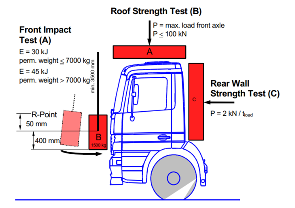
Fig. 1. UN/ECE R29 [23]
The rigid pendulum with a striking surface of 2500 mm x 800 mm and a mass of 1500 kg ± 250 kg must be so positioned, that in its vertical position the centre of gravity is 50 +5/-0 mm below the R-Point of the driver’s seat. This is different to the preceding version of this regulation where the vertical position of the centre of gravity was 150 +5/-0 mm below the R-Point of the driver’s seat with a maximum height above ground of 1400 mm. This change leads to the fact that the pendulum now impacts the front panel of the cab with most vehicle versions, while in the preceeding version of ECE-R29 mostly the cab suspension or the frame front end was impacted [6].
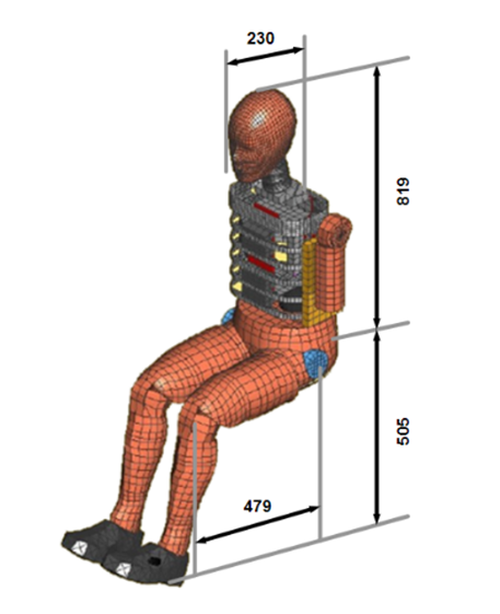
Fig. 2. Standard size specifications of the driver
2.4 Application of the Finite Element Method in Constructing Frontal Collision Problems
2.4.1 Model setup
The problem is analyzed and evaluated through simulation results obtained from the Hypermesh software with the Radios solver. The collected results are compared with theoretical foundations to assess the reliability of the model and the software results. The steps are carried out according to the following procedure:
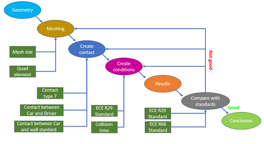
Fig. 3. Steps to perform the process
In this study, based on commonly used 29-seat buses, the team utilized a bus model designed based on popular 29-seat buses currently in operation in Vietnam, such as the Thaco TB82S, Hyundai County, and Isuzu Samco Growin Li, among others. The common feature of these newer bus models is the use of a multi-link frame, which enhances the frame's resistance to bending and provides high durability [20].
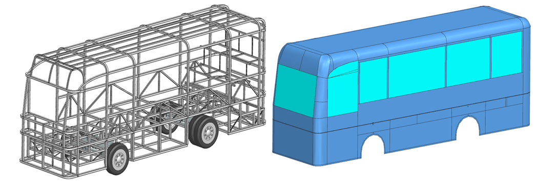
Fig. 4. The frame and body structure model of the passenger bus
Above is the overall model of the 29-seat passenger bus, with the total length, width, and height measuring 7945x2256x3105 mm. The frame structure of the right and left side walls is arranged with four large doors on each side, separated by 60x60x4 mm steel box sections. Below the windows, the body is reinforced with several diagonal steel box sections of 40x40x4 mm to increase the rigidity of the side walls. The model retains one-third of the front section, as per ECE R29 standards, where the vehicle is fixed. The model is divided into 748,479 elements, including the frame and body, with a mesh size of 10 mm [21].
The mechanical properties of each steel grade used in the simulation are presented in the table below. Each part is defined through an image card, with material characteristics set using Pshell to represent sheet material and Ishell (24:QEPH shell formulation). The thickness varies for different components and is specified individually through the thickness settings. The materials used for the structural frame are Q235 steel, while the underframe structure is made of Q345 steel, as shown below [7]:
Table 1. The frame material properties
|
Material |
Young’s Modulus (GPa) |
Poisson’s ratio |
Density (kg/mm3) |
Ultimate strength (MPa) |
|
Q235 |
210 |
0.3 |
7.85*10-6 |
235 |
|
Q345 |
210 |
0.3 |
7.85*10-6 |
345 |
2.4.2 Frontal Collision Setup According to ECE R29 Standard
In the collision problem, it is crucial to set up the collision relationships between the objects. According to the ECE R29 standard[6,18], the vehicle is positioned stationary under the impact of a pendulum, as shown in Figure 1. The interactions between the finite elements in the vehicle model use contact type 7 in Hypermesh software. The advantage of this contact type is that its stiffness remains constant and increases when the node passes through the middle surface of the body, addressing the issue of poor contact often encountered when using contact type 5 or type 3[5].
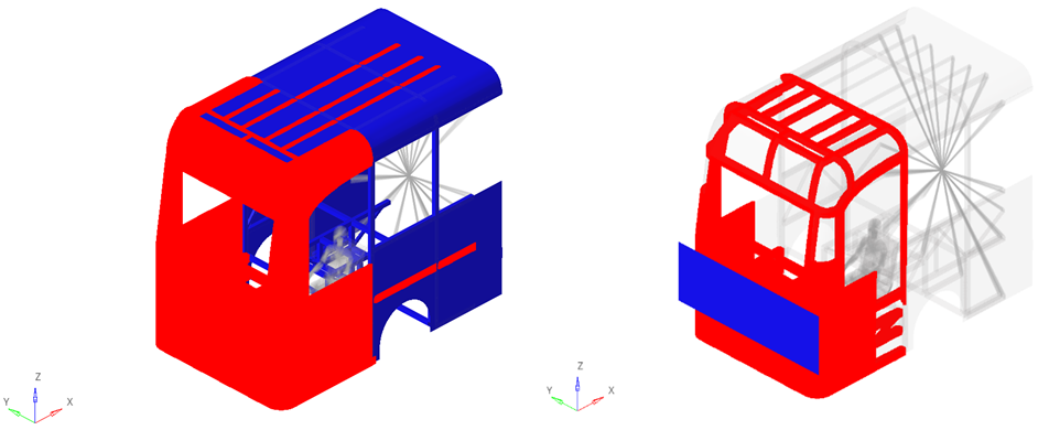
Fig. 5. Contact between the vehicle model and the pendulum according to the ECE R29 standard [24]
More importantly, to evaluate the impact on the driver, the effect of the vehicle on the driver’s body parts is considered, involving a total of 7 contacts.
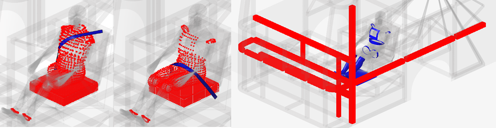
Fig. 6. Contact between the driver, the seatbelt, and the vehicle frame
3 Result and discussion
When a vehicle crashes, its kinetic energy from motion is converted into internal energy, which is the energy responsible for mechanical deformation in the vehicle’s structure, such as the body, frame, and other systems. The total kinetic energy lost is equal to the total internal energy gained due to these deformations.
In this problem, the total energy is:
\[E=\frac{1}{2}\times m\times v^2=\frac{1}{2}\times2355\times\left(\frac{8280}{1000}\right)^2=8,073.{10}^7\ mJ\]
According to the simulation results, the energy graph is shown as follows:
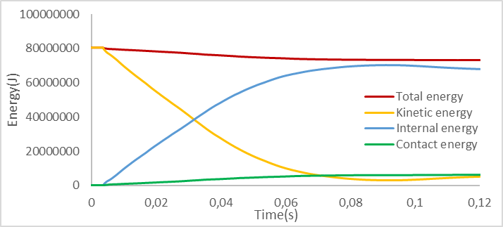
Fig. 7. Energy graph
The initial total energy of the system was 8.073*10⁷mJ. After 0.12 seconds of collision, it decreased to 7.324*10⁷mJ, corresponding to a 9.28% reduction. This loss is primarily attributed to the use of non-uniform mesh elements, which introduced computational inaccuracies. Furthermore, a significant portion of the lost energy, approximately 6.42*10⁶mJ (85.7% of the total loss), was converted into contact energy, encompassing sound, heat, and other forms of dissipation generated during the collision. An energy error within the range of 5–10% is considered acceptable; therefore, the observed reduction in total kinetic energy is within permissible limits. The simulation results exhibit an accuracy 92% when compared with theoretical predictions.
3.1 Original vehicle evaluation results
In the initial vehicle case, the maximum stress concentration on the body shell is 457.299MPa, while the maximum stress concentration in the frame area is 456.571MPa. Compared to the standard stress of 500MPa, both the frame and body shell meet the strength requirements for collision safety.
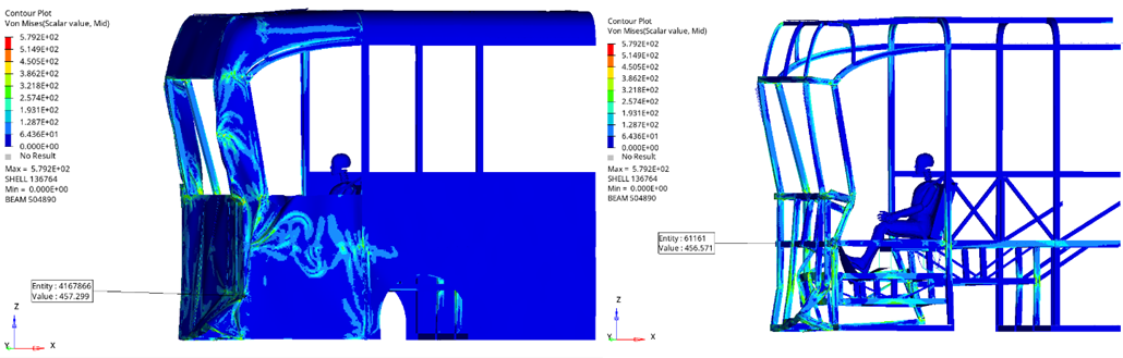
Fig. 8. Vehicle frame and body after collision
The driver’s space is measured between node 510359 and node 498972, with an initial distance of 1219.117 mm. After the collision, the vehicle's frame deformed, intruding into the driver's cabin, reducing the available space with an intrusion level of 510.228 mm.
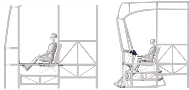
Fig. 9. Vehicle cabin before and after collision
For the driver, the area that experiences the earliest and most significant force impact is the right foot area. Therefore, this area is the focus of the evaluation and analysis.
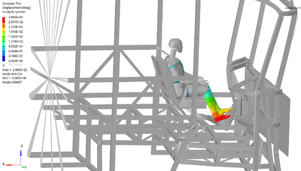
Fig. 10. Displacement of the driver’s leg
As shown in Figure 12, the graph of the force applied to the right femur exhibits a noticeable fluctuation from 0 N to 2976.3N within the time frame of 0 to 0.12 seconds, indicating a strong impact on the femur. Specifically, the peak force reaches approximately 2976.3N at 0.05s, while another peak appears around 2000N at 0.07s. The force begins to increase from 0.01s and fluctuates significantly between 0.02s and 0.10s. After reaching its peak, the force tends to decrease gradually and stabilize below 1000N from 0.08s to 0.12s. According to the ECE R94 standard, the force applied to the femur[22] in the initial vehicle setup remains within the standard limits (less than 9.07kN at the first 10ms and less than 7.58kN after the first 10ms)[8].
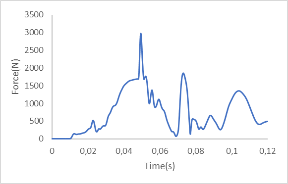
Fig. 11. Force–time graph acting on the right femur
The second area that needs to be evaluated is the driver’s neck, as this area is often subjected to significant forces due to the sudden inertial impact during a collision.
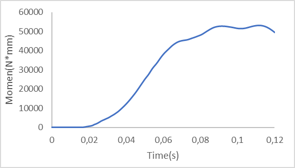
Fig. 12. Graph of Moment Acting on the Neck along the Y-axis
According to the ECE R94 standard, the bending moment in the neck area along the Y-axis should not exceed 57Nm[8]. However, in the initial vehicle case, the measured maximum bending moment is 53108 Nmm. Although it is below the safety standard, it still poses significant risks if the collision intensity increases.
3.2 Addition of Energy Absorption Bar
In the study by Erdem Acar et al. [9], a bus front bumper model was built and evaluated according to the ECE R29 [12]. The model focuses on the bumper beam component, which is 1112 mm long, 5 mm thick and made of steel. The energy absorbing box is designed with closely packed hexagons, 64 mm high, 2 mm thick. Combined with the front reinforcement bar, the energy absorbing bar adopts a corrugated structure, commonly used in bent tubes to enhance the collision energy dissipation capacity of the front bumper system [10].

Fig. 13. Bumper beam
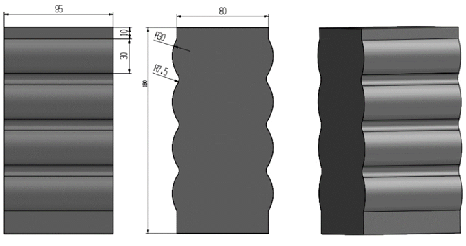
Fig. 14. Crash box
3.3 Discussion
Figure 15 shows that the maximum stress is 540.5MPa when the impact is made at the stiffener position, and this maximum value appears at the energy absorbing bar position. This is reasonable because the main function of the energy absorbing bar is to deform and absorb force as follows:
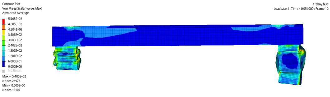
Fig. 15. Stress distribution on the front bumper beam
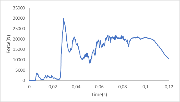
Fig. 16. Force–time graph acting on the front bumper beam
The energy absorption bar begins to take the impact from the early stages (0–0.02s) with the force gradually increasing. At approximately 0.025s, the force reaches its peak (~30,000N), indicating that the bar starts to deform significantly. After that, the force fluctuates and decreases but remains high after 0.03s, reflecting the energy absorption and dissipation process. By around 0.10s, the force continues to decrease, indicating that the energy absorption process is nearly complete.
As shown in Figure 18, at the location with the greatest intrusion into the driver's cabin, the measured value is 424.167mm, a 16.88% reduction compared to the case when the vehicle does not have a bumper. With an intrusion of 424.167mm, the vehicle's frame system still maintains the survival space, meaning it does not exceed the ECE R66 standard (600mm)[11].
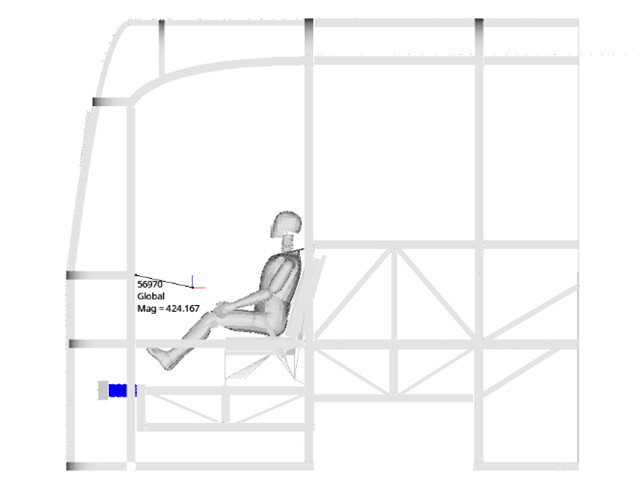
Fig. 17. Intrusion into the cabin with bumper installed.
In the case with the bumper, the maximum force applied to the femur is reduced to 2049.6N, a decrease of approximately 31.13% compared to the case without a bumper.
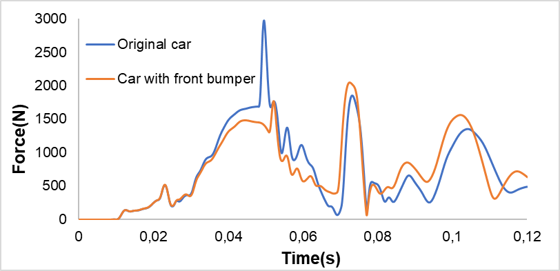
Fig. 18. Femur impact force in both scenarios.
In the case of the improved vehicle, the trend of the force applied to the femur has significantly decreased, with a reduction of nearly 900N compared to the initial vehicle. The oscillations after 0.06s tend to be higher than those of the original vehicle, as the energy absorption bar has reached its limit and can no longer absorb further impact, causing the inertia to be directly transmitted to the driver. However, despite this, the forces remain within the safety zone and have been significantly reduced compared to the original model.
For the neck area of the original vehicle, the magnitude of the bending moment along the Y-axis on the driver’s neck is close to the safety standard. By adding the front bumper, the graph shows the following trend:
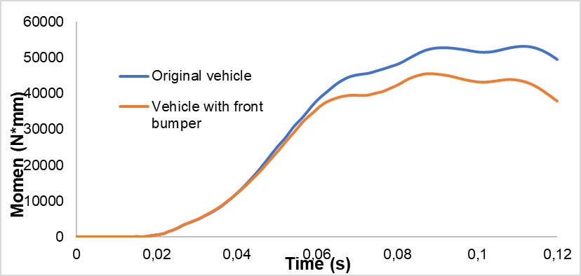
Fig. 19. Momen Y-axis neck moment graph of the driver in both scenarios
Thus, the maximum bending moment along the Y-axis applied to the driver’s neck has decreased to 45594.3Nmm, a reduction of 14.14% compared to the original vehicle. The maximum bending moment is entirely within the ECE R94 standard and shows a lighter trend than the original model at all times.
This study has certain limitations that should be recognized. The simulation was carried out under simplified assumptions, including a stationary vehicle and ideal operating conditions. While these assumptions help isolate key variables and make the analysis more manageable, they do not fully reflect the complexity of real-world collision events. In actual scenarios, factors such as moving vehicles, varying speeds, driver response times, road surface conditions, and weather can significantly influence outcomes. Therefore, the results of this study should be viewed as indicative rather than definitive. To improve practical applicability, future work should incorporate dynamic conditions and validate the findings against experimental crash data or real accident case studies.
4 Conclusion
Through the simulation and evaluation of the 29-seat passenger bus model according to the ECE R29 standard, combined with standards such as ECE R66 for evaluating the driver’s cabin and ECE R94 for evaluating driver safety, the results show that the addition of a front bumper on the passenger bus is feasible and provides positive outcomes for the new generation of buses with multi-link frames. The intrusion level was reduced by 16.88% and meets the safety standard with an intrusion of 424.17mm compared to the standard of 500mm. Additionally, the force applied to the femur decreased significantly by 31.13% compared to the initial model, and the bending moment applied to the driver’s neck along the Y-axis reduced by 14.14% compared to the original vehicle. Thus, the addition of a front bumper with the design used in this study significantly reduces the impact of a frontal collision on the driver, enhancing safety, particularly for 29-seat passenger buses that frequently travel on the roads.
Acknowledgements
No external funding was received.
References
- Tedros, A.G., Bloomberg, M.R. (2023). Global status report on road safety 2023. WHO. Available: https://www.who.int/teams/social-determinants-of-health/safety-and-mobility/global-status-report-on-road-safety-2023, accessed Apr. 12, 2025.
- Holenko, K., et al. (2024). Validation of Frontal Crashworthiness Simulation for Low-Entry Type Bus Body According to UNECE R29 Requirements. MDPI, 14(13). https://doi.org/10.3390/app14135595.
- Lopes, R., et al. (2022). FEM Modelling of Passive Safety Solutions for Buses. Proceedings of the 5th Meeting of the Young Researchers of LAETA, Portugal. https://doi.org/10.13140/RG.2.2.23234.25285.
- Luu, N.P.T. (2019). Analysis of Bus Structural Performance During Full Frontal Impact. 2019 International Conference on System Science and Engineering (ICSSE), Dong Hoi, Vietnam: IEEE, pp. –, https://doi.org/10.1109/ICSSE.2019.8823416.
- Quan, V.H., Tung, N.T., Ngoc, N.A., Minh, D.N. (2025). Application of Finite Elements to Analysis of Side Collision Problems of Vehicle: A Case Nissan Rogue 2020 SUV Model. Journal of the Turkish Society of Automotive Engineers, 9(1), pp. 81–88. https://doi.org/10.30939/ijastech..1581465.
- Raich, H. Safety Analysis of the New Axtros Megaspace Cabin According to ECE-R29/02. Available: https://lsdyna.ansys.com/wp-content/uploads/attachments/safety-analysis-of-the-new-actros-megaspace-cabin.pdf, accessed Apr. 12, 2025.
- Tam, N.T., Thanh, N.C., Sy, N.V., Danh, L.T., Nam, N.D. (2021). Optimal Design Structure of Sleeper Bus to Enhance Injury Safety of Human in Frontal Collision. 2nd Annual International Conference on Material, pp. 70–77. https://doi.org/10.1007/978-3-030-69610-8_9.
- UN/ECE. (2022). Regulation No 94 — Uniform provisions concerning the approval of vehicles with regard to the protection of the occupants in the event of a frontal collision. Available: https://unece.org/sites /default/files/ 2024-07/R094r4e.pdf
- Acar, E., Yilmaz, B., Güler, M.A., Altin, M. (2020). Multi‑fidelity crashworthiness optimization of a bus bumper system under frontal impact. Journal of the Brazilian Society of Mechanical Sciences and Engineering. https://doi.org/10.1007/s40430-020-02572-3.
- UN/ECE. (2007). Regulation No 66 — Uniform technical prescriptions concerning the approval of large passenger vehicles with regard to the strength of their superstructure. Available: https://op.europa.eu/en/publication-detail/-/publication/69a98949-88be-4e2a-bcb7-d26d4e8778b3/language-en, accessed Apr. 12, 2025.
- Rooppakhun, S., & Bua-Ngam, S. (2013). Finite Element Analysis of High-Decker Bus Frontal Impact Based on ECE-Regulation No.29. Advanced Materials Research. https://doi.org/10.4028/www.scientific.net/ AMR.658.464.
- Deulgaonkar, V.R., et al. (2020). Crash Analysis of Bus Body Structure using Finite Element Analysis. International Journal of Vehicle Structures & Systems. https://doi.org/10.4273/ijvss.12.3.17.
- Lopes, R., et al. (2022). Passive Safety Solutions on Coach according ECE R29. Transportation Research Procedia. https://doi.org/10.1016/j.trpro.2022.05.053.
- Afripin, M., & Zainudin, M.F. (2023). Frontal Impact on Bus Superstructure as per UNECE R29 and NCAP. Transportation Research Procedia. https://doi.org/10.1016/j.trpro.2023.05.054.
- Li, Q.M., et al. (2006). Impact Behavior of Structures. International Journal of Impact Engineering. https://doi.org/10.1016/j.ijimpeng.2005.08.002.
- Jones, N. (2010). Structural Impact. Elsevier. https://doi.org/10.1016/B978-0-08-098248-2.00001-9.
- Mamalis, A.G., et al. (2003). Crashworthiness of Structural Materials. Thin-Walled Structures. https://doi.org/10.1016/S0263-8223(03)00044-7.
- Zhao, Y., et al. (2017). Crash Simulation and Impact Analysis. Crashworthiness of Transportation Systems. https://doi.org/10.1016/B978-0-12-809951-3.00011-4.
- Song, J., & Chen, W. (2011). Crash Analysis of Composite Structures. Composite Structures. https://doi.org/10.1016/j.compstruct.2011.01.010.
- Sinha, S.K., & Kukreti, A.R. (1997). Dynamic Analysis of Vehicles. International Journal of Impact Engineering. https://doi.org/10.1016/S0734-743X(97)00018-1.
- Carleone, J. (2015). Finite Element Modeling for Crash Simulations. Crash Safety. https://doi.org/10.1016/B978-0-12-417056-8.00004-4.
- UNECE, 2010, Regulation No. 94. Uniform provisions concerning the approval of vehicles with regard to the protection of the occupants in the event of a frontal collision. https://eur-lex.europa.eu/legal-content/EN/TXT/PDF/?uri=CELEX%3A42010X0528%2803%29
- UN/ECE R29. https://lsdyna.ansys.com/wp-content/uploads/attachments/safety-analysis-of-the-new-actros-megaspace-cabin.pdf
- Rogério Lopes, Nuno V. Ramos, Rafael Cunha, Ricardo Maia. Passive Safety Solutions on Coach according ECE R29: Experimental and Numerical analyses. Procedia Structural Integrity, volume 42, 2022. https://doi.org/10.1016/j.prostr.2022.12.148.
Conflict of Interest Statement
All authors declare that they have no conflicts of interest.
Author Contributions
Data Availability Statement
The data presented in this study are available on request from the corresponding author.
Supplementary Materials
No supplementary materials are provided with this manuscript.