Original Scientific Paper, Volume 23, Number 2, Year 2025, No 1275, pp 314-321
Received: Jan 08, 2025 Accepted: Apr 24, 2025 Published: Jun 16, 2025
DOI: 10.5937/jaes0-55883
COMPUTATIONAL ANALYSIS OF HIP PROSTHESIS: IMPACT OF SHAPE AND MATERIAL ON MECHANICAL PERFORMANCE
Abstract
Hip implants play a crucial role in restoring mobility and reducing pain in patients with hip joint disorders. The design and material selection of the implant stem significantly influence its mechanical performance and longevity. This study presents a comparative finite element analysis of circular and rectangular hip implant stems to evaluate their structural behaviour under static loading conditions. The implant stems were modeled using CREO 11.0 and analysed using Ansys 2023 R2, with a load of 2300 N applied to simulate real-world conditions. Two materials—Cobalt Chromium (CoCr) and Ti–6Al–4V alloys—were considered to assess their mechanical properties. The results indicate that rectangular stems exhibited lower total deformation, von Mises stress, and strain compared to circular stems, making them structurally superior. Among the materials analysed, CoCr demonstrated better mechanical performance, reducing stress concentration and potential failure risks. Additionally, metal-on-metal (MoM) configurations showed enhanced durability over metal-on-polyethylene (MoPE). These findings suggest that a rectangular CoCr stem in a MoM configuration is optimal for improving implant longevity and reducing revision surgery rates. The study underscores the importance of optimized implant geometry and material selection in total hip arthroplasty. Future research should explore dynamic loading conditions and patient-specific implant designs to enhance clinical outcomes further.
Highlights
- Finite element analysis reveals rectangular hip implant stems demonstrate superior structural performance (lower deformation, stress, and strain) compared to circular stems.
- Cobalt Chromium (CoCr) alloy exhibits better mechanical performance in hip implants than Ti-6Al-4V, reducing stress concentration and failure risks.
- Metal-on-metal (MoM) hip implant configurations show enhanced durability over metal-on-polyethylene (MoPE), with rectangular CoCr stems in MoM configurations being optimal for longevity.
Keywords
Content
1 Introduction
1.1 Background
Total hip replacement (THR) is a medical process in which a damaged hip portion is replaced with a prosthetic implant, primarily to relieve pain and restore function in patients suffering from conditions such as osteoarthritis, rheumatoid arthritis or hip fractures. THR is particularly important in orthopedic surgery because of its ability to ease life for patients, particularly older adults and younger individuals seeking relief from debilitating hip pain. The procedure enhances mobility for daily activities such as walking, sitting, standing, stair climbing, descending, squatting, cycling and performing religious prayers, while also reducing the need for long-term pain management [1][2]. The long-term success of the total hip arthroplasty (THA) relies on the ability of the implant to withstand dynamic lifestyle requirements and remains functional for decades without the need for revision operation. The effective design of the hip implant focuses on optimizing load transfer and stress distribution to reduce the risk of release and failure of components [3]. The critical role of design in minimizing revision procedures due to aseptic loosening, a thorough understanding of mechanics and longevity of the implant is necessary [4]. Since the demand for hip replacement continues to grow, to improve surgery and reduce the need for revisions is essential.
1.2 Components in hip implant
Hip implant assembly consist of Stem the lower component, above is spherical femoral head, liner which acts as a bearing surface and top component is acetabular cup as mentioned in figure 1. Advancements in THA have introduced various bearing surfaces, like metal-on-polyethylene (MoPE), ceramic-on-polyethylene (CoP), metal-on-metal (MoM), ceramic-on-ceramic (CoC), and ceramic-on-metal (CoM) configurations [5].
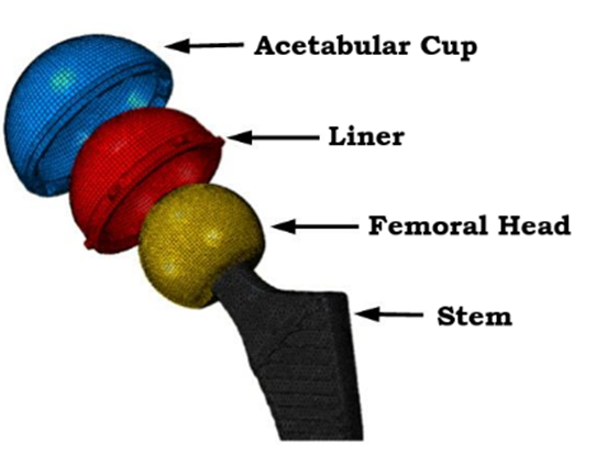
Fig. 1. Schematic of femoral THR implementation. Reproduced from [6] under CC 3.0
These developments have led to modern designs with features such as femoral head along with stem, liner and an acetabular cup, available in a variety of shapes and sizes. In this study, only MoM and MoPE configuration were considered to establish the design parameters such as shapes and sizes, selection of materials, coefficient of friction and contact pressure for suitable hip implant.
1.3 Finite element analysis
In this work, circular and rectangular shaped stem designs were modelled using CREO 11.0. The common choices for hip implant stems were Ti–6Al–4V and cobalt chromium alloys materials due to its optimal mechanical characteristics and biocompatibility [7]. Total displacement and von Mises stress for all stems were evaluated using Ansys 2024 R2. A static load of 2300 N is applied on femoral head as per standards. Various models with different interfaces of CoCr alloys, Ti–6Al–4V and UHMWPE were considered in this work [8]. Femoral heads with diameter ranges from 22 mm to 36 mm have been considered based on individual body anatomy [9]. In this work, a constant femoral head diameter of 32 mm with 4 mm acetabular cup and 2 mm backing cup were considered. In the first model, the UHMWPE acetabular liner with the metal femoral head was considered. In the second model, the CoCr acetabular cup is covered by a metal backing cup. A recent study found that PEEK liner material against UHMWPE exhibited excellent wear performance [10]. Mechanical characterization under static conditions using the FEA was performed [11] . The distribution of stress across implants and strains was observed for all models. The cartilage layer was observed to spread the load, resulting in a decline of deformation and the maximum stress in the implants. Straight stems were considered for the study as shown in figure 1. In another study, applied load to the femoral head center were acting on the greater trochanter [12]. Contact force with a coefficient of friction f = 0.08 within femoral head and acetabulum was modelled. Static load boundary conditions of ASTM F2996-13 were followed in the study [13]. The boundary conditions for daily activities like sitting, standing, stair climbing, descending, squatting and cycling vary and should be applied accordingly in FEA simulations [2][14].
Circular and rectangular shapes were modelled with straight stem as shown in figure 2. FEA was conducted to perform static analysis on models using Ansys 2023 R2 with different material combinations according to ASTM standards and boundary conditions. Initially stems were analyzed for the best suited stem materials between CoCr and Ti-6Al-4V alloy. In the second part complete implant is considered along with femoral head, acetabular cup and backing cup with different materials combinations.
2 Materials and methods
The shape and size are the key features in the hip design, especially while designing the stem. Circular and rectangular shapes for stems were considered in the analysis for study. A collared straight stem and curve on the lateral side were considered for study as shown in figure 2. All hip implant CAD models were created using CREO 11.0 and analysis was conducted using Ansys 2023 R2 to estimate von Mises stress and strain with the application and total deformation.
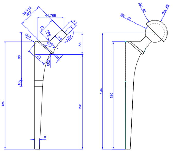
Fig. 2. Detail drawing for hip stem and assembled hip implant [15]
The selection of materials was driven by the need to balance mechanical performance, biocompatibility, wear resistance and overall longevity of the hip implant. Each material possesses distinct properties that play a key role in the function of the hip implant, increase mobility restoration and reduce pain in patients with total hip arthroplasty. The properties of different materials considered in this work are shown in Table 1.
Table 1. Materials used and properties for stems [16][17][18]
|
Sl |
Materials |
Young's modulus [GPa] |
Density [gm/cm3] |
Poisson's ratio |
Ultimate Tensile strength [MPa] |
|
1. |
Ti–6Al–4V |
114 |
4.5 |
0.31 |
930 |
|
2. |
CoCr Alloy |
200 |
8.5 |
0.30 |
1503 |
|
3. |
UHMWPE |
0.963 |
0.95 |
0.31 |
48 |
2.1 Mesh generation & boundary conditions
The accuracy of computational results is significantly influenced by size of the mesh [19]. The unstructured mesh is considered as shown in figure 3 with mesh size of 1mm. Mesh size is considered from our own previously published work [20]. The total number of nodes and elements are given in table 2.

Fig. 3. (a) Stem as specified by ASTM F2996-1 and meshed model, (b) Complete hip implant and meshed model
Table 2. Total number of nodes and elements in complete implant with femoral head
|
SI |
Hip Implant Assembly |
Number of Nodes |
Number of Elements |
|
1. |
Circular |
4,39,314 |
5,05,015 |
|
2. |
Rectangular |
6,77,513 |
7,32,059 |
Boundary and load conditions were applied as per ASTM F2996-13 [21]. As per standards, the hip stem was divided into three parts from the top surface of the stem based on the total length of the stem. The first section was made from top face center of femoral spherical head which measured as 80 mm. Next incision was made 10 mm below the first incision. The bottom portion of stem was confined on all surfaces distal to the second portion of stem. Fixing the hip stem in this way confirms that extreme stresses do not occur in the concerned area due to rigid fixation. A static analysis was performed for two considered designs with the same boundary.
3 Results and discussion
Initially static structural analysis is performed for the stems considering CoCr alloy and Ti–6Al–4V alloy materials under the load of 2300 N. Table 3 summarized the analysis outcomes for the CoCr alloy and Ti–6Al–4V alloy hip stem.
Table 3. Structural analysis outcomes of CoCr alloy and Ti–6Al–4V alloy hip stem
|
Sl |
Stem Material |
Stem shape |
Total deformation in mm |
Equivalent von Mises stress in MPa |
Equivalent strain in mm/mm |
|
1. |
CoCr alloy |
Circular |
0.36 |
723.3 |
0.003 |
|
2. |
Rectangular |
0.31 |
537.2 |
0.002 |
|
|
3. |
Ti–6Al–4V |
Circular |
0.63 |
715.3 |
0.003 |
|
4. |
Rectangular |
0.54 |
533.8 |
0.004 |
From the results, it can be observed that the stem with rectangular shape showed the minimum displacement and von Mises stress regardless of CoCr and Ti-6Al-4V material. Secondly, stem with CoCr as material showed minimum displacement and von Mises stresses compared to Ti–6Al–4V stem. Total deformation, von Mises stress and elastic strain for the rectangular shaped stem with CoCr is shown in figure 4.
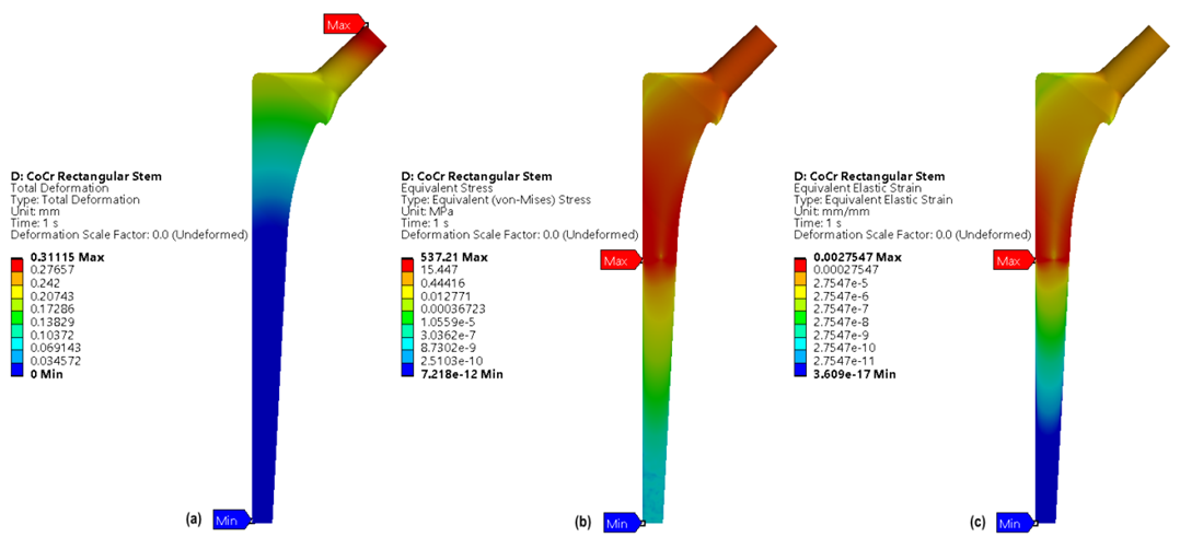
Fig. 4. Rectangular Stem with CoCr, (a) Total deformation, (b) von Mises stress, (c) Elastic strain
Usually, hip implant is made up of either MoM or MoPE. The table 4 shows the different combinations of the materials used in hip implants. These material combinations are evaluated to know the best suited material combinations when complete hip implant is considered.
Table 4. Various material combinations of hip implant assembly
|
Sl |
Material Combination |
Stem shape |
Stem |
Head |
Acetabular Liner |
Backing cup |
|
1. |
MoM |
Circular |
CoCr |
CoCr |
CoCr |
CoCr |
|
2. |
Ti–6Al–4V |
CoCr |
||||
|
3. |
Rectangular |
CoCr |
CoCr |
|||
|
4. |
Ti–6Al–4V |
CoCr |
||||
|
5. |
MoPE |
Circular |
CoCr |
UHMWPE |
||
|
6. |
Ti–6Al–4V |
UHMWPE |
||||
|
7. |
Rectangular |
CoCr |
UHMWPE |
|||
|
8. |
Ti–6Al–4V |
UHMWPE |
A force of 2300 N was applied on the backing cup and center of femoral head which acted as a fully constrained design. Structural analysis was carried out on two variants MoM and MoPE of hip implant to determine the best combination of materials. Table 5 summarized the analysis outcomes for the different combinations considered in complete hip implant along with femoral head, acetabular cup and backing cup.
Table 5. Structural analysis outcomes of MoM and MoPE hip implant assembly
|
Sl |
Material Combination |
Stem shape |
Total deformation in mm |
Equivalent von Mises stress in MPa |
Equivalent strain in mm/mm |
|
1. |
MoM |
Circular |
0.43 |
728.8 |
0.003 |
|
2. |
0.61 |
344.3 |
0.003 |
||
|
3. |
Rectangular |
0.37 |
536.8 |
0.002 |
|
|
4. |
0.75 |
720.6 |
0.008 |
||
|
5. |
MoPE |
Circular |
0.43 |
728.8 |
0.0036 |
|
6. |
0.75 |
767.9 |
0.0068 |
||
|
7. |
Rectangular |
0.43 |
728.8 |
0.0036 |
|
|
8. |
0.66 |
965.3 |
0.008 |
Table 5, shows that MoM rectangular shaped hip implant exhibited the minimum displacement over all the combinations of the materials considered. However, the circular shaped MoM implant exhibited less von Mises stresses compared to all the designs. Total deformation, von Mises stress and elastic strain for hip implant with a rectangular CoCr stem were shown in figure 5.

Fig. 5. MoM with a rectangular CoCr stems (a) Total deformation, (b) von Mises stress, (c) Elastic strain
Cobalt Chromium alloy, Ti–6Al–4V alloy and UHMWPE are widely used hip implant materials [22]. Design requirements are very critical for hip implants to minimize revision joint operations to prevent aseptic loosening [4]. Previous studies indicate that determining an optimized design and material selection is challenging, as analyzing available results on a common basis remains difficult. Different structural models composed of UHMWPE, CoCr and Ti–6Al–4V alloys were analyzed under static conditions using FEA, revealing 0.1 mm deformation in implants made from Ti–6Al–4V [23]. Studies have shown that the maximum von Mises stress of 137 MPa, below the 850 MPa yield strength of Ti–6Al–4V and CoCr which ensured the safety of the hip prosthesis under static conditions [4]. Additionally, hip implant made of Ti–6Al–4V showed that at a load of 2500 N, the resulting stress in the implant is 256 MPa [24].
In this work, all the models are assessed in terms of total deformation and stress-strain with respect to ASTM F2996-13 standards [25]. Models showed a stress less compared to ultimate strength under a static load of 2300 N. Rectangular stems showed the best result with a minimum total deformation of 0.31 mm, a von Mises stress of 537.2 MPa and elastic strain of 0.002 mm for the CoCr stem.
Comparable results have been reported for stem and hip implant assembly. An implant with an acetabulum liner made of MoM was found to have less deformation compared to the MoPE material. In addition, the hip implant assembly consisting of MoM with a rectangular CoCr stem has the lowest displacement of 0.37 mm, von Mises stress of 536.8 MPa and elastic strain of 0.002 mm compared to all other designs. The CoCr material stem and acetabular cup made of MoM configuration are safe to use as implants ensuring optimal surgical results and reducing the need of revision surgery. In vivo studies and clinical trials will be essential to validate these findings and ensure the practical applicability of proposed materials.
The analysis is performed under static load conditions, which may not fully represent the dynamic stresses encountered in day-to-day scenarios such as walking, running, Sitting, stair climbing. Dynamic analysis would bring more accurate knowledge to the integration of factors, such as the sliding distance and the contact pressure between the femoral head and the acetabular cup, which can evaluate wear and provides a more detailed understanding of the implant performance under realistic gaits load conditions [4]. The wear assessment of the implant component can be validated using coordinate measuring machine (CMM) [26]. Recent studies conducted during a dynamic load have shown promising results; The above findings could therefore be further validated by dynamic analysis for increased accuracy [27].
The findings of this study provide the basis for future research focused on optimizing materials such as PEEK, and exploring various material combinations for hip implants [10]. Advances in surface modifications and coatings could further increase wear resistance and support better osseointegration. In addition, the development of designs of implants specific to the patient through additive production can lead to the new generation hip implants with excellent functionality and lower failure, which eventually transforms orthopedic implant technology and improve results in patients with hip arthroplasties.
4 Conclusions
This study comprehensively evaluates the mechanical performance of circular and rectangular hip implant stems using finite element analysis. The analysis reveals that rectangular stems outperform circular stems in terms of reduced total deformation, von Mises stress and elastic strain, regardless of the material used. Among the materials analyzed, cobalt chromium alloy exhibited superior mechanical properties compared to Ti–6Al–4V alloy, making it the preferred choice for hip implant stems. Furthermore, the study emphasizes the suitability of metal-on-metal configurations over metal-on-polyethylene due to their enhanced durability and lower deformation under static load conditions. The findings highlight the importance of optimizing stem geometry and material selection in hip implant design to enhance implant longevity and minimize revision surgeries. Rectangular stems, particularly those made of CoCr in MoM configurations, emerge as the optimal combination for total hip arthroplasty. However further dynamic analysis is required with different dynamic gait cycles to optimize these designs.
Acknowledgements
The authors would like to thank the Department of Aeronautical and Automobile Engineering, Manipal Institute of Technology, Manipal Academy, Manipal for the computing resources provided to carry out this research work.
References
- A.T. Alpkaya, M. Yılmaz, A.M. Şahin, D.Ş. Mihçin, Investigation of stair ascending and descending activities on the lifespan of hip implants, Med. Eng. Phys. 126 (2024). https://doi.org/10.1016/j.medengphy.2024.104142.
- S. Mihcin, A.M. Sahin, M. Yilmaz, A.T. Alpkaya, M. Tuna, S. Akdeniz, N.C. Korkmaz, A. Tosun, S. Sahin, Database covering the prayer movements which were not available previously, Sci. Data 10 (2023) 1–15. https://doi.org/10.1038/s41597-023-02196-x.
- F.C. Chang, J.P. Hung, Y.L. Lai, Finite element analysis on the mechanical effect of a roughened stem for cemented hip prosthesis, 2009 WRI World Congr. Comput. Sci. Inf. Eng. CSIE 2009 3 (2009) 254–258. https://doi.org/10.1109/CSIE.2009.931.
- K. Chalernpon, P. Aroonjarattham, K. Aroonjarattham, Static and Dynamic Load on Hip Contact of Hip Prosthesis and Thai Femoral Bones, Int. J. Mech. Mechatronics Eng. 9 (2015) 11–15.
- D. Dowson, New joints for the Millennium: Wear control in total replacement hip joints, Proc. Inst. Mech. Eng. Part H J. Eng. Med. 215 (2001) 335–358. https://doi.org/10.1243/0954411011535939.
- X. Hua, J. Li, L. Wang, Z. Jin, R. Wilcox, J. Fisher, Contact mechanics of modular metal-on-polyethylene total hip replacement under adverse edge loading conditions, J. Biomech. 47 (2014) 3303–3309. https://doi.org/10.1016/j.jbiomech.2014.08.015.
- J.V. Corda, K.N. Chethan, B. Satish Shenoy, S. Shetty, N. Shyamasunder Bhat, M. Zuber, Fatigue Life Evaluation of Different Hip Implant Designs Using Finite Element Analysis, J. Appl. Eng. Sci. 21 (2023) 896–907. https://doi.org/10.5937/jaes0-44094.
- M.F.D. Emre Celik1, Furkan Alemdar1, Murat Bati1, and ¸Senay M. Onur Alp Buyukbayraktar1, K. N. Chethan2, Mustafa Kara1, Mechanical Investigation for the Use of Polylactic Acid in Total Hip Arthroplasty Using FEM Analysis, in: 2022: p. 174.
- J. Girard, Femoral head diameter considerations for primary total hip arthroplasty, Orthop. Traumatol. Surg. Res. 101 (2015) S25–S29. https://doi.org/10.1016/j.otsr.2014.07.026.
- A.T. Alpkaya, Ş. Mihçin, The Computational Approach to Predicting Wear: Comparison of Wear Performance of CFR-PEEK and XLPE Liners in Total Hip Replacement, Tribol. Trans. 66 (2023) 59–72. https://doi.org/10.1080/10402004.2022.2140727.
- Ş. Mihçin, S. Ciklacandir, TOWARDS INTEGRATION OF THE FINITE ELEMENT MODELING TECHNIQUE INTO BIOMEDICAL ENGINEERING EDUCATION, Biomed. Eng. Appl. Basis Commun. 34 (2022). https://doi.org/10.4015/S101623722150054X.
- Z. Horak, P. Kubovy, J. Horakova, Does mechanical loading influence development of osteoarthritis in hip joint?, Comput. Methods Biomech. Biomed. Engin. 14 (2011) 263–264. https://doi.org/10.1080/10255842.2011.595227.
- M. Dharme, A. Kuthe, Effect of geometric parameters in the design of customized hip implants, J. Med. Eng. Technol. 41 (2017) 429–436. https://doi.org/10.1080/03091902.2017.1323967.
- G. Bergmann, A. Bender, J. Dymke, G. Duda, P. Damm, Standardized loads acting in hip implants, PLoS One 11 (2016) 1–23. https://doi.org/10.1371/journal.pone.0155612.
- G.P. Crean, Surgical Technique, Br. Med. J. 1 (1956) 1172. https://doi.org/10.1136/bmj.1.4976.1172-a.
- J. Reginald, M. Kalayarasan, K.N. Chethan, P. Dhanabal, Static, dynamic, and fatigue life investigation of a hip prosthesis for walking gait using finite element analysis, Int. J. Model. Simul. 43 (2023) 797–811. https://doi.org/10.1080/02286203.2023.2212346.
- H. Göktaş, E. Subaşi, M. Uzkut, M. Kara, H. Biçici, H. Shirazi, K.N. Chethan, Ş. Mihçin, Optimization of Hip Implant Designs Based on Its Mechanical Behaviour, in: 2022: pp. 37–43. https://doi.org/10.1007/978-3-030-86297-8_4.
- J.V. Corda, C. K N, S. Bhat N, S. Shetty, S. Shenoy B, M. Zuber, Finite element analysis of elliptical shaped stem profile of hip prosthesis using dynamic loading conditions, Biomed. Phys. & Eng. Express 9 (2023) 65028. https://doi.org/10.1088/2057-1976/acfe14.
- A.T. Alpkaya, S. Mihcin, Sensitivity Analysis of Wear on Metal-On-Metal Bearing Couples via Verification of Numeric and Analytic Methods, Hittite J. Sci. Eng. 11 (2024) 57–67. https://doi.org/10.17350/hjse19030000332.
- Chethan.K.N, M. Zuber, S. Bhat N, S. Shenoy B, Optimized trapezoidal-shaped hip implant for total hip arthroplasty using finite element analysis, Cogent Eng. 7 (2020). https://doi.org/10.1080/23311916.2020.1719575.
- ASTM, F 2996-20 Standard Practice for Finite Element Analysis ( FEA ) of Non-Modular Metallic Orthopaedic Hip Femoral Stems, ASTM Int. Conshohocken, PA, Www.Astm.Org (2020) 1–11. https://doi.org/10.1520/F2996-13.2.
- S.M. Darwish, A.M. Al-Samhan, Optimization of artificial hip joint parameters, Materwiss. Werksttech. 40 (2009) 218–223. https://doi.org/10.1002/mawe.200900430.
- H. bo Jiang, Static and Dynamic Mechanics Analysis on Artificial Hip Joints with Different Interface Designs by the Finite Element Method, J. Bionic Eng. 4 (2007) 123–131. https://doi.org/10.1016/S1672-6529(07)60024-9.
- K. Colic, A. Sedmak, A. Grbovic, U. Tatic, S. Sedmak, B. Djordjevic, Finite element modeling of hip implant static loading, Procedia Eng. 149 (2016) 257–262. https://doi.org/10.1016/j.proeng.2016.06.664.
- K.N. Chethan, N. Shyamasunder Bhat, M. Zuber, B. Satish Shenoy, Finite element analysis of different hip implant designs along with femur under static loading conditions, J. Biomed. Phys. Eng. 9 (2019) 507–516.
- L. Wang, X. Peng, C. Sun, H. Wang, D. Li, J. Zhu, Z. Jin, S. Mihcin, C. Liu, THE DETERMINATION of the VOLUMETRIC WEAR for SURGICALLY RETRIEVED HIP IMPLANTS BASED on CMM, J. Mech. Med. Biol. 16 (2016) 1–13. https://doi.org/10.1142/S0219519416500597.
- T. Joshi, R. Sharma, V.K. Mittal, V. Gupta, G. Krishan, Dynamic Analysis of Hip Prosthesis Using Different Biocompatible Alloys, ASME Open J. Eng. 1 (2022). https://doi.org/10.1115/1.4053417.
Conflict of Interest Statement
There are no conflicts affecting the research.
Author Contributions
Data Availability Statement
There is no dataset associated with the study or data is not shared.
Supplementary Materials
There are no supplementary materials to include.