Original Scientific Paper, Volume 23, Number 2, Year 2025, No 1268, pp 236-242
Received: Oct 03, 2024 Accepted: Jan 24, 2025 Published: Jun 16, 2025
DOI: 10.5937/jaes0-53910
MATHEMATICAL MODELING OF THE PROCESS OF APPLYING A GAS-THERMAL COATING TO LONG RODS OF QUARRY SPECIAL EQUIPMENT
Abstract
To solve the problem of improving the wear and corrosion resistance of parts in mechanical engineering, the method of gas-thermal spraying of coatings is often used. The process of gas-thermal spraying makes it possible to obtain a protective coating by atomizing molten or heated material using a high-speed gas or plasma flow. As part of the study, a mathematical model describing the physical processes occurring during the spraying process was developed. The mathematical model makes it possible to determine the optimal modes of the process, providing the obtaining of coatings of a given thickness and properties. The developed mathematical model will allow process engineers to calculate process parameters more accurately and obtain coatings with specified characteristics. The maximum adhesive strength of the gas-thermal coating Х18Н10Т (4.78 MPa) is observed at the maximum difference between the burner nozzle area and the sprayed area.
Highlights
- The study focuses on using gas-thermal spraying to improve the wear and corrosion resistance of mechanical engineering parts, particularly long rods of quarry special equipment.
- Mathematical modeling is presented as a powerful tool for optimizing parameters like torch-to-substrate distance, particle flow rate, nozzle area, and plasma temperature to achieve desired coating characteristics (hardness, adhesion, porosity).
- The adhesive strength of gas-thermal coatings changes with variations in burner nozzle area, sprayed area, mass of substance deposited, and mass of sprayed substance.
Nomenclature
LHDC - linear inhomogeneous differential control;
ISO – international system organization.
Keywords
Content
1 Introduction
The essence of the processes of gas-thermal coating application consists in the formation of a directed flow of dispersed particles of the sprayed material, ensuring their transfer to the surface of the workpiece and the formation of a coating layer [1]. The coating is created due to the adhesion that occurs when particles collide on the surface of the base [2]. These particles are powder or can be obtained by melting and gas crushing of the original material (plasticizer) [3]. Particle acceleration is acquired in various high-temperature gas environments [4]. Heating of the sprayed material is carried out to increase the plasticity and adhesive capacity of the particles [5].
The analysis of operating conditions of the main parts of quarry equipment at the mining industry enterprises in Karaganda region shows that 60-80% of hydraulic cylinder rods lose their serviceability. Characteristic defects of rod elements are risks, burrs, wear and tear, and more than 60% of defects are caused by corrosion.
The conducted analysis of works on quality assurance of quarry equipment parts allows to assume that by using technologically simple, mobile and economically justified technology of restoration of the surface layer of machine parts it is possible to significantly increase the resource of rods and reduce the cost of equipment operation. Important in this case is the choice of the method of coating spraying and the determination of optimal spraying parameters using mathematical modeling.
Mathematical modeling of cladding [6] and spraying coatings [7] is a powerful tool for optimizing process parameters and obtaining coatings with specified properties.
Modeling allows determining the optimal values of such parameters as the distance from the torch to the substrate, particle flow rate, nozzle area, plasma temperature and others to obtain a coating with the required characteristics (hardness, adhesion, porosity, etc.) [8]. Thanks to modeling, virtual experiments can be conducted, which significantly reduces the time and cost of developing new technologies.
The model makes it possible to assess the quality of the resulting coating even before the start of the experiment, which helps to avoid rejects and reduce production costs. Modeling helps to develop new methods of gas-thermal spraying and materials for coatings [9].
While making a mathematical process model of the manufacturing process, it is necessary to determine the factors affecting the response [10]. Too small torch nozzle to the part surface can cause overheating of the substrate and particles, which can cause pore formation, cracking and reduced coating adhesion [11]. If the distance to the substrate is too large - the particles may cool down before reaching the substrate, resulting in a decrease in their kinetic energy and a deterioration in surface adhesion [12].
Low flow rate of sputtering particles can lead to insufficient coating density and pore formation [13]. High flow rate of the sprayed particles can cause damage to the substrate surface and deteriorate the adhesion of the coating [14].
The small nozzle area of the sputter limits the amount of material to be sputtered and can lead to inhomogeneous coating [15]. Large nozzle area of the sputter nozzle can cause flow turbulence and reduce coating accuracy [16].
When the particle mass is small, the sprayed coating can easily deviate from the trajectory and may not reach the substrate [17]. When the particle mass is large, pore formation may occur and the coating densities may decrease [18].
Thus, the aim of the article is to establish the dependence of coating thickness on the mass, flow rate of the sprayed particles and the distance of the torch installation.
2 Materials and methods
To describe the gas-thermal spraying (Figure 1), a mathematical technological process model for calculating the distance y of the torch installation to the part to be sprayed was proposed, based on Newton's second law with the initial flow velocity ϑ0 of the sprayed material.
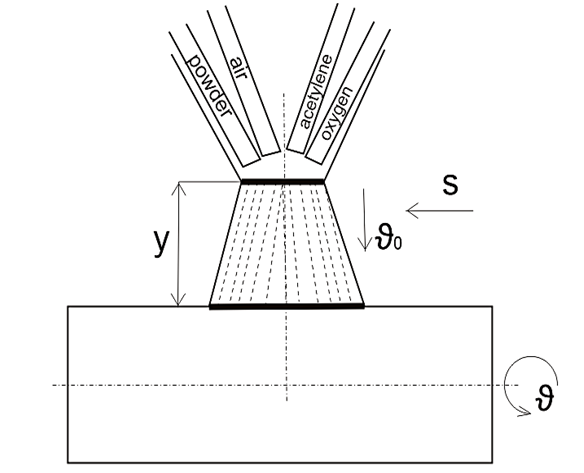
Fig. 1. Scheme of gas-thermal spraying, y – burner mounting distance; particle velocity of the sprayed material; s – burner speed (feed); rotational speed of the part to be sprayed
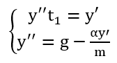
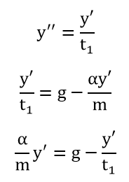
The flow of particles of the sprayed material is most significantly affected by the forces of aerodynamic drag and gravity [19]. To solve the mathematical model, a differential equation with initial conditions was made up y(0)=0; y'(0)=ϑ0 :
| (1) |
To solve the differential control, a second-order linear inhomogeneous differential control (LHDC) has been formulated as follow:
| (2) |
To solve the equation (2) of the second order, a linear homogeneous differential control (LHDC) of the second order was composed, which has the following form:
| (3) |
3 Results and discussion
To solve the equation (3), the characteristic equation has the following form:
| (4) |
Solving equation (4) we find the roots of the characteristic equation K1 and K2 which are equal to:
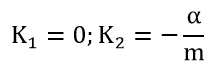 |
Substituting the roots of the solution of equation (4) we obtain the general solution of the LHDC, which has the following form:
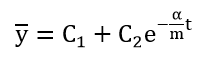 |
(5) |
where C1 and C2 – integration constants.
Since K1=0 we obtain a partial solution of equation (2) which has the form:
| (6) | |
| (7) | |
| (8) |
Solving equation (2) we find its solution:
 |
The total solution of equation (2) is equal to the sum of equation (5) and equation (6), which we write in the following form:
| (9) |
Based on the initial conditions (0)=0 y'(0)=ϑ0 , we find the values C1 and C2.
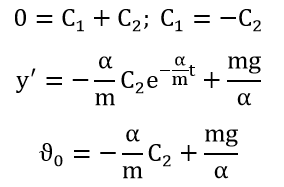 |
|
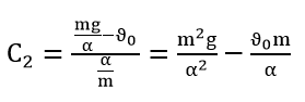 |
(10) |
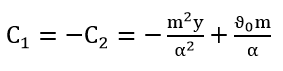 |
(11) |
The obtained values of the integration constants C1 and C2 are substituted into equation (9) and we obtain the following mathematical relationship:
| (12) |
where m – mass of substance passing through the burner nozzle per unit time;
g – free fall acceleration;
α – proportionality factor;
ϑ0 – flow velocity of the sprayed material particles;
t – processing time.
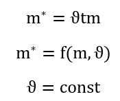
Graphically, equation (12) is presented in Figure 2.
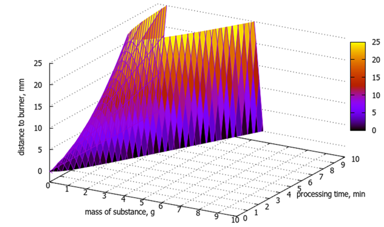
Fig. 2. Dependence of the burner installation height on the substance mass and processing time
The coefficient α depends on the particle flow rate and can be determined experimentally.
To determine the proportionality coefficient α analytically, the dependence of the impact force on the sprayed surface can be drawn up as follows:
| (13) |
To form a quality layer on the surface of the workpiece, it is necessary to take into account the impulse of the impact force of the particles of the sprayed material with the surface of the workpiece:
| (14) |
Based on expressions (13) and (14) we derive the following system of equations:
 |
(15) |
Solving the system of equations (16) we obtain:
 |
|
| (17) |
where t1 – time of flight of the particle from the nozzle to the part to be sprayed.
Thus, the proportionality factor α can be found analytically
The height y can be adjusted as a function of time. If, for example, the time must not exceed the permissible value t0 in order to ensure a quality spraying, then y is expressed as follows:
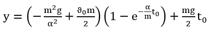 |
(18) |
Depending on the distance of the torch nozzle from the workpiece, a coating layer is formed on the sprayed surface, which is graphically represented in Figure 3.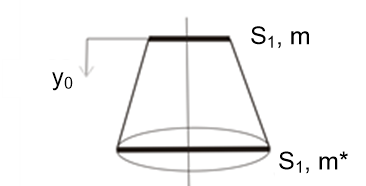
Fig. 3. Coating layer
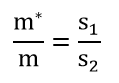
To determine the required coating layer at a certain distance of the burner nozzle from the workpiece, the following dependence has been established:
 |
|
 |
(19) |
where – mass of substance deposited on the part;
S1 – burner nozzle area;
S2 – sprayed area;
m – the mass of the sprayed substance that flies out of the burner.
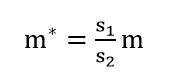
Per unit of time sprayed area of the substance S2 m*:
 |
|
| (20) |
Based on equations (18) and (19), depending on the required sputtering mass, it is possible to change the nozzle diameter and burner mounting height.
The limitation of the study is that the mathematical model is based on a number of simplifying assumptions. It does not take into account flow turbulence, material heterogeneity, and particle interactions during the application of a gas-thermal coating.
Experimental studies have shown that when changing the burner nozzle area, sprayed area, mass of substance deposited on the part, mass of the sprayed substance that flies out of the burner, the adhesive strength of samples with a gas-thermal coating change (Table 1).
The adhesive strength was assessed using the pull-off method (ISO 4624). This method involves measuring the minimum tensile stress required to separate or tear the coating in a direction perpendicular to the surface being painted.
|
a) |
b) |
|
c) |
d) |


Fig. 4. Samples after testing with Х18Н10Т coating; a) sample No. 1; b) sample No. 2; c) sample No. 3; d) sample No. 4
Table 1. Adhesive strength of samples with gas-thermal coating Х18Н10Т
| Sample | Burner nozzle area, s1, mm | Sprayed area, s2, mm | Mass of substance deposited on the part, g | Mass of the sprayed substance that flies out of the burner, m, | Square, m2 | Strenght, N | Adhesive strength, МPа |
| №1 | 3,14 | 12,56 | 12 | 10 | 5,0×10⁻⁴ | 1044 | 4,78 |
| №2 | 3,14 | 19,625 | 14 | 12 | 5,6×10⁻⁴ | 1212 | 4,62 |
| №3 | 19,625 | 23,74 | 14 | 12 | 5,2×10⁻⁴ | 1212 | 4,29 |
| №4 | 19,625 | 28,26 | 12 | 10 | 4,9×10⁻⁴ | 1044 | 4,69 |
According to the data in Table 1, it can be concluded that the greater the difference between the parameters s1 and s2, the higher the adhesive strength of the thermal spray coating.
4 Conclusions
As a result of the conducted research the following can be noted:
1) The following parameters influence the distance of burner installation to the workpiece: the mass of substance passing through the burner nozzle per unit time, the flow rate of particles of the sprayed material, and the processing time;
2) The proportionality factor α depends on the particle flow rate and can be determined experimentally;
3) The proportionality factor α can be estimated analytically using equation (17);
4) The diameter of the burner nozzle has a significant influence on obtaining the required coating layer and sputtering spot;
5) Creation of a complex mathematical model allows to take into account all these factors and optimize the process of gas-thermal spraying to obtain coatings with specified properties.
References
- Tejero-Martin D., Rezvani Rad M., McDonald A., Hussain T. Beyond Traditional Coatings: A Review on Thermal-Sprayed Functional and Smart Coatings J Therm Spray Tech, 28, 2019, pp. 598–644
- Kovalevskaya Z., Zaitsev K., Klimenov V. Research of Adhesion Bonds Between Gas-Thermal Coating and Pre-Modified Base IOP Conf. Series: Materials Science and Engineering, 142, 2016, 012087
- Nouri A., Sola A. Powder morphology in thermal spraying Journal of Advanced Manufacturing and Processing, 2019, e10020
- Yin Sh., Meyer M., Li W., Liao H., Lupoi R. Gas Flow, Particle Acceleration, and Heat Transfer in Cold Spray: A review Journal of Thermal Spray Technology, Volume 25, 2016, pp. 874–896
- Kretinin V., Teppoev A., Sokolova V. Modeling features of the technological process of forestry machines parts strengthening by the method of gas-thermal spraying Journal of Physics Conference Series, Vol 2131 (2), 2021, 022034
- Zharkevich О., Nurzhanova O., Zhunuspekov D., Naboko Ye., Buzauova Toty, Abdugaliyeva G., Mateshov A., Bessonov A. Determination of Optimal Hardfacing Modes for Recovering Electric Motor Shafts Tehnički vjesnik, 30, 3, 2023, pp. 951-95
- Panwar V., Chawla V., Grove N. A Review on different thermal spray coating process for industrial applications International Journal of Latest Trends in Engineering and Technology, Special Issue AFTMME-2017, pp. 064-068
- Zhetessova G., Zharkevich O., Pleshakova YE., Yurchenko V., Platonova Ye., Buzauova T. Building mathematical model for gas-thermal process of coating evaporation Metalurgija, 55, 2016, 1, pp. 63-66
- Bobzin K., Wietheger W., Knoch M. Development of Thermal Spray Processes for Depositing Coatings on Thermoplastics J Therm Spray Tech, 2021, 30, pp. 157–167
- Plotnikova I. V., Redko L. A., Chicherina N. V., Efremova O. N., Serebryakov S. G. Study of the technological process parameters basis on a mathematical model IOP Conf. Series: Materials Science and Engineering, 457, 2018, 012021
- Saydakhmedov R.Kh., Saidakhmedova G.R. The impact of thermal barrier coatings on the protective properties of turbine blades of gas turbine engine International scientific journal, Volume 2, Issue 5, 2023, pp. 64 - 71
- Olt Ju., Maksarov V., Krasnyy V. Provision of adhesion strength of gas-thermal coatings on piston rings of quarry transport engines Journal of Mining Institute, Vol. 229, 2018, pp. 77-83
- Xue M., Chandra S., Mostaghimi J., Salimijazi H. R. Formation of Pores in Thermal Spray Coatings due to Incomplete Filling of Crevices in Patterned Surfaces Plasma Chem Plasma Process, 2007, 27, pp. 647 - 657
- Huang R., Fukanuma H. Study of the Influence of Particle Velocity on Adhesive Strength of Cold Spray Deposits JTTEE5 21, pp. 541–549
- Barroso G. Ceramic Coatings by Thermal Spraying – a Comparison between High Velocity Oxy-Fuel and Atmospheric Plasma Spraying Ceramic Applications, 9, 2021, pp. 1 - 5
- Łatka L., Pawłowski L., Winnicki M., Sokołowski P., Małachowska А., Kozerski S. Review of Functionally Graded Thermal Sprayed Coatings Appl. Sci. 2020, 10, 5153
- Pawlowski L. Suspension and solution thermal spray coatings Surface & Coatings Technology 203, 2009, pp. 2807–2829
- Shukla Rajesh Kumar, Alok Kumar, Rajesh Kumar, Digvijay Singh, Arvind Kumar Numerical study of pore formation in thermal spray coating process by investigating dynamics of air entrapment Surface and Coatings Technology, 2019, 378
- Ionut Claudiu Roata, Catalin Croitoru, Alexandru Pascu, Elena Manuela Stanciu Photocatalytic coatings via thermal spraying: a mini-review AIMS Materials Science, 2019, Volume 6, Issue 3, pp. 335-353.
Conflict of Interest Statement
The authors declare no conflicts of interest.
Author Contributions
Data Availability Statement
There is no dataset associated with the study or data is not shared.
Supplementary Materials
All materials are published in this article. No additional data.