Volume 24 number 1 article 1322 pages: 144-155
Received: Sep 09, 2026 Accepted: Dec 24, 2026 Available Online: Jan 07, 2026 Published: Mar 02, 2026
DOI: 10.5937/jaes0-61381
SIMPLE EQUATION FOR WALL-COLUMN CONTACT LENGTH TO ESTIMATE THE LATERAL STRENGTH OF REINFORCED CONCRETE FRAMES WITH MASONRY INFILL WALLS
Abstract
This work introduces an analytical approach for assessing the seismic capacity of brick masonry infills within reinforced concrete frame structures by the use of a diagonal strut model. The model demonstrates that when the column experiences flexural displacement and the masonry wall endures shear deformation, separation or contact transpires between the masonry infill and the column. The contact height between the masonry infill and column was determined based on the compatibility of lateral displacements of both elements. As a result, a simple equation of contact length between infill and column to determine the lateral strength of masonry infill was employed to calculate the strut width of the masonry infill. The lateral strength for several reinforced concrete frame structures with brick masonry infills was determined using the simplified contact length equation. Furthermore, the analytical results were validated using lateral strength of structure models as outcomes of the pushover method. The results showed that the lateral forces of the structures were relatively similar between the analytical and pushover methods. It suggests that the strut model and the simplified wall-column contact height can be used to estimate the lateral strength of masonry infill in reinforced concrete structures.
Highlights
- Implementation of an analytical diagonal strut model for estimating the lateral strength of reinforced concrete frames with brick masonry infill.
- Proposed a simplified equation for determining the wall-column contact length, which is essential for calculating the strut width of masonry infill.
- Verified the lateral strength of brick masonry infilled frames using results obtained from the pushover analysis method.
Content
1 Introduction
Brick masonry infills are elements that fill the reinforced concrete (RC) structural frame and are only considered to be non-structural components; thus, they are not included in the seismic design calculations. However, studies on RC frame structures with brick infill walls under the earthquake simulation modelling have demonstrated the potential of masonry infills in enhancing the seismic performance of RC frame structures as reported by Mehrabi et al. [1] who conducted an experiment on RC frame structures with masonry infills to assess their structural performance, and found that panels with full masonry infills can significantly increase the stiffness and lateral strength of frame structures. Similarly, Chaker and Cherifati [2] observed that masonry walls in frame structures increased the lateral stiffness of RC buildings. Another study by Maidiawati et al. [3, 4] tested RC frame structures with and without brick masonry infills and discovered that brick masonry infills in frame structures can increase the overall lateral strength of the structure by four times that of frame structures without walls, but the structure's ductility is cut in half. Numerous researchers, such as Holmes [5], Smith and Carter [6] Mainstone [7, 8], Leuchars and Scrivener [9], Paulay and Priestley [10], Suku and Radja [11], and Maidiawati and Sanada [4] have conducted several analytical techniques to estimate the lateral load capacity of brick walls. They developed an analytical model to determine the effective width of a diagonal strut and analyse interactions between the masonry infill and frame.
This study applied the analytical model developed by Maidiawati and Sanada [4] to assess the seismic capacity of RC frames with masonry infills. The model proposes that the width of the strut depends on the contact height of the masonry wall against the RC frame structure. When lateral deformation occurs, the contact height is determined by the height of the brick infill attached to the RC frame. Estimating the contact height can be derived using numerical techniques particularly by applying static equilibrium equation of compatible lateral displacement that occurs between masonry walls and boundary frame. However, the numerical technique requires long calculation steps and many assumptions. Therefore, a simplified contact length equation is proposed to improve the efficiency of determining the contact height between the wall and column.
2 Materials and methods
2.1 Analytical model of masonry infilled frames
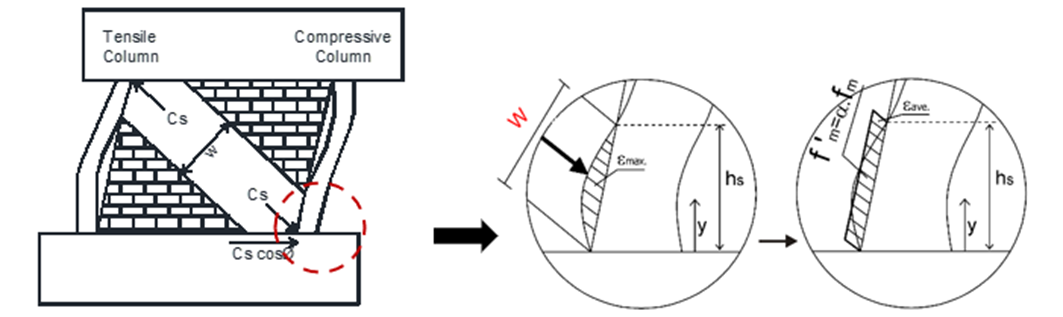
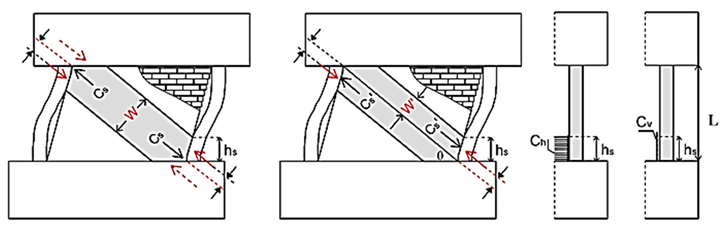
Maidiawati and Sanada have introduced an analytical model to assess the lateral strength of masonry infill walls within reinforced concrete frame structures, as thoroughly documented in the reference [4]. In this model, when the column undergoes flexural displacement and the masonry wall suffers shear deformation, separation or contact occurs between the infill and the column, as seen in Fig. 1(a). Fig. 1(b) demonstrates that deformation produces a stress distribution at the contact area denoted by fm, which may be substituted by an equivalent rectangular stress block. The averaged compressive strength f’m is determined by multiplying the uniaxial compressive strength of the infill fm by a reduction factor (α=0,65). The force Cs, reliant upon the dimensions of the struts, can be computed by measuring the width W of the diagonal strut and the thickness t of the infill as described in Eq. (1) which defines W in terms of hs as given in Eq. (2). In Fig. 2, the compressive force Cs' operates on the top and bottom of the compressive/tensile column and may be broken down into lateral and vertical components ($c_h = t f_m' \cos^2 \theta$) and ($c_v = t f_m' \sin \theta \cos \theta$) acting on the column (see Fig. 2(c)) with the contact height of hs.
|
(a) Diagonal strut of infill |
(b) stress distribution at interface of infill-column |
Fig. 1. Model strut of masonry infill
|
(a) Strut width |
(b) Diagonal compression force |
(c) Distributed strut force |
Fig. 2. Diagonal forces of infill
|
$C_s = W t f_m'$ |
(1) |
|
$W = 2 h_s \cos \theta$ |
(2) |
The hs is calculated based on the lateral displacement on the column and infill under a lateral load. The lateral displacement is determined using Eqs. (3) and (4), respectively, for 0 ≤ y ≤ hs and hs ≤ y ≤ L [2].
|
$\delta_c(y) = \frac{1}{EI}\left( \frac{1}{24} C_h y^4 - \frac{1}{6} Q_u y^3 + \frac{1}{2} M_u y^2 \right)$ |
(3) |
|
$\delta_c(y) = \frac{1}{EI}\left[ \left(\frac{1}{6} C_h h_s - \frac{1}{6} Q_u\right) y^3 + \left(\frac{1}{2} M_u - \frac{1}{4} C_h h_s^2\right) y^2 + \frac{1}{6} C_h h_s^3\, y - \frac{1}{24} C_h h_s^4 \right]$ |
(4) |
Mu is the ultimate moment at the base of the column (Eq. 5), and Qu is the ultimate shear force of the column (Eq. 6).
| $M_u = 0.8\, a_t \sigma_y D + 0.5\, N D \left(1 - \frac{N}{b D F_c}\right)$ | (5) |
| $Q_u = \frac{2 M_u}{L} + C_h h_s - \frac{C_h h_s^2}{L} + \frac{C_h h_s^3}{3 L^2}$ | (6) |
where E is the modulus of elasticity, σy is the longitudinal reinforcement tensile stress, D is the column height, N is the axial load, y is the column height under review, b is the column width, and Fc is the concrete compressive strength.
The lateral displacement of the masonry infill is determined using Eq. (7), assuming that the infill's shear strain, θi, is uniform. By using Eqs. (3) or (4) and (7), which are provided with δc(y)=δi(y), one may determine the point of intersection of the lateral displacement between the column and the infill, yi.
|
$\delta_i(y) = \theta_i \, y = \frac{\delta_c(y=L)}{L} \, y$ |
(7) |
2.2 The evaluated masonry infilled frame structures
2.2.1 The model structures
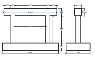
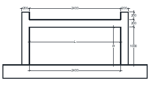
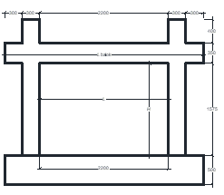
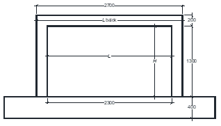
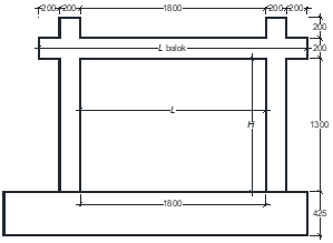
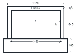
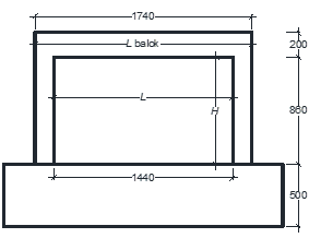
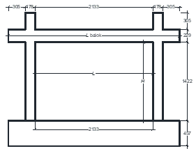
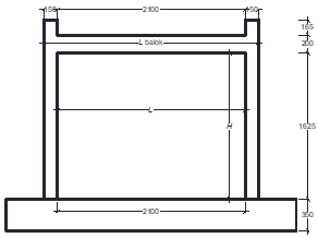
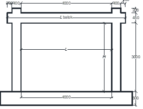
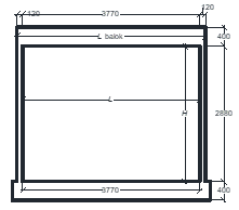
Twelve RC frame structures with brick infill, a single-panel RC frame structure with fully infilled masonry walls were adopted from several references [12]-[22], were evaluated the lateral strength of their infill by using the diagonal strut model. The cross-sectional dimensions of columns, beams, masonry wall and thickness of walls (tw) of evaluated structure models, are presented in Table 1. The material properties of the concrete’s compressive strength (fc’), yield strength of rebars (fy) and the masonry wall compressive strength (fm) of the structures are included in the table 1.
Table 1. The dimensions and material properties of the evaluated Structure Models
|
Structure models |
Columns |
Beam |
Masonry infill |
Sketch drawing and references |
|
1 |
Cross section: 125x125 (mm) Main bars: 4D10 Hoop: Ø4-50 fc’= 49.9 MPa fy= 619.7 MPa |
Cross section: 200x200 (mm) Main bars: 4D13 Hoop: Ø6-50 fc’= 49.9 MPa fy= 582.4 MPa |
Cross section: 60x30x13 (mm) tw =30 (mm) fm=10.3 MPa |
Source: Maidiawati et al. [12] |
|
2 |
Cross section: 150x150 (mm) Main bars: 6Ø10 Hoop: Ø6-75 fc’= 24.0 MPa fy= 620 MPa |
Cross section: 150x200 (mm) Main bars: 4D10 Hoop: Ø6-75 fc’= 24.0 MPa fy= 620 MPa |
Cross section: 250x120x200 (mm) tw=120 (mm) fm=4.0 MPa
|
Source: Dautaj A.D, et al. [13] |
|
3 |
Cross section: 300x300 (mm) Main bars: 8Ø16 Hoop: Ø10-150 fc’= 35.9 MPa fy= 428.8 MPa |
Cross section: 300x350 (mm) Main bars: 8Ø16 Hoop: Ø10-150 fc’= 35.9 MPa fy= 428.8 MPa |
Cross section: 190x90x56 (mm) tw=90 (mm) fm=10.3 MPa
|
Source: Kim, M., and Yu, E. [14] |
|
4 |
Cross section: 200x200 (mm) Main bars: 4Ø8 Hoop: Ø6-80 fc’= 30 MPa fy= 430 MPa |
Cross section: 200x250 (mm) Main bars: 6Ø10 Hoop: Ø6-90 fc’= 30 MPa fy= 430 MPa |
Cross section: 250x120x120 (mm) tw=120 (mm) fm=3.1 MPa
|
Source: Bergami, A. V., and Nuti, C. [15] |
|
5 |
Cross section: 200x200 (mm) Main bars: 12Ø10 Hoop: Ø6-75 Hoop: Ø6-150 fc’= 58 MPa fy= 550 MPa |
Cross section: 120x200 (mm) Main bars: 12Ø6 Hoop: Ø6-100 fc’= 58 MPa fy= 550 MPa |
Cross section: 250x120x95 (mm) tw=120 (mm) fm=17.5 MPa |
Source: Penava,D. et al, [16] |
|
6 |
Cross section: 178x178 (mm) Main bars: 8Ø13 Hoop: Ø6-64 fc’= 26.9 MPa fy= 420 MPa |
Cross section: 152x229 (mm) Main bars: 4Ø16 Hoop: Ø6-76 fc’= 26.9 MPa fy= 420 MPa |
Cross section: 194x92x92 (mm) tw=92 (mm) fm=14.2 MPa |
Source: Stavridis, A., and Shing, P. B., [17] |
|
7 |
Cross section: 110x110 (mm) Main bars: 4Ø5.5 Hoop: Ø5.5-50 fc’= 25.9 MPa fy= 360 MPa |
Cross section: 120x200 (mm) Main bars: 4Ø5.5 Hoop: Ø5.5-75 fc’= 25.9 MPa fy= 360 MPa |
Cross section: 314x78,5x157 tw=78.5 (mm) fm=3.8 MPa |
Source: Soulis, D. J. [18] |
|
8 |
Cross section: 150x150 (mm) Main bars: 8Ø6 Hoop: Ø2.7-33.3 fc’= 27.9 MPa fy= 348 MPa |
Cross section: 100x200 (mm) Main bars: 8Ø6 Hoop: Ø2.7-33.3 fc’= 27.9 MPa fy= 348 MPa |
Cross section: 252x63x126 (mm) tw=63 (mm) fm=6.0 MPa |
Source: Soulis, V. J [18] |
|
9 |
Cross section: 178x178 (mm) Main bars: 8Ø13 Hoop: Ø6-64 fc’= 29.5 MPa fy = 420 MPa |
Cross section: 152x229 (mm) Main bars: 4Ø16 Hoop: Ø6-76 fc’= 29.5 MPa fy= 420 MPa |
Cross section: 194x92x92 (mm) tw=92 (mm) fm=15.6 MPa |
Source: Dewobroto, W. [19] |
|
10 |
Cross section: 150x150 (mm) Main bars: 8Ø8 Hoop: Ø4-100 fc’= 20 MPa fy (Ø8) =400 MPa fy (Ø4) =500 MPa |
Cross section: 150x200 (mm) Main bars: 6Ø8 Hoop: Ø4-100 fc’= 20 MPa fy (Ø8) =400 MPa fy (Ø4) =500 MPa |
Cross section: 300x200x150 (mm) tw=200 (mm) fm=1.7 MPa
|
Source: Braz-Cesar, M. T [20] |
|
11 |
Cross section: 400x400 (mm) Main bars: 4Ø16 Hoop: Ø8-100 fc’= 33.5 MPa fy (Ø16) = 420 MPa fy (Ø8) =480 MPa |
Cross section: 200x450 (mm) Main bars: 4Ø16 Hoop: Ø8-100 fc’= 33.5 MPa fy (Ø16) = 420 MPa fy (Ø8) =480 MPa |
Cross section: 240x200x110 (mm) tw=200 (mm) fm=3.5 MPa |
Source: Cai, G., and Su. Q. [21] |
|
12 |
Cross section: 120x250 (mm) Main bars: 3Ø13+2Ø10 Hoop: Ø6-100 fc’= 19.8 MPa fy(Ø13) =412 MPa fy (Ø6) =228 MPa |
Cross section: 120x400 (mm) Main bars: 6Ø13 Hoop: Ø6-100 fc’= 19.8 MPa fy (Ø13) =412 MPa fy (Ø6) =228 MPa |
Cross section: 250x150x150 (mm) tw=150 (mm) fm=2.5 MPa |
Source: Bahreini, V. [22] |

3 Results and discussion
3.1 Lateral strength of masonry infill
According the analytical model as described above, the contact length and the strut width of the masonry infill of the structure models can be evaluated as exhibited in Table 2. The lateral strength of the masonry infills at yield (Vi(y)) were calculated using the Eq. (8).
| $v_{i(y)} = C_s \cos \theta = W t f_m' \cos \theta$ | (8) |
Assuming the lateral displacement of the frame is equal to the lateral displacement of the masonry infill, the lateral force of the structure, Vf(y), is a cumulative shear force of compressive column (Qu) from equation 6, the shear force between the masonry infill and the beam (= ½ Cs cos ![]() ) and shear force on tensile column Qt. Consequently, the lateral strength of masonry infill and infilled frame structure at yield of evaluated model structures are resumed in table 2.
) and shear force on tensile column Qt. Consequently, the lateral strength of masonry infill and infilled frame structure at yield of evaluated model structures are resumed in table 2.
Table 2. Contact length, strut width, strength of masonry infills and infilled frames
|
Structure models |
Column height, L (mm) |
Contact length, hs (mm) |
Strut width, W (mm) |
Lateral strength of infill, Vi(y) (kN) |
Lateral strength of infilled frame, Vf(y) (kN) |
|
1 |
750 |
234.7 |
360.6 |
93.6 |
122.5 |
|
2 |
1000 |
298.5 |
551.1 |
158.3 |
189.7 |
|
3 |
1575 |
427.3 |
694.9 |
339.8 |
433.9 |
|
4 |
1300 |
328.0 |
571.0 |
119.4 |
141.7 |
|
5 |
1300 |
326.4 |
529.3 |
585.7 |
695.6 |
|
6 |
1341 |
320.9 |
543.5 |
390.7 |
430.6 |
|
7 |
845 |
197.1 |
340.6 |
56.3 |
64.4 |
|
8 |
860 |
252.3 |
433.2 |
90.8 |
110.2 |
|
9 |
1422 |
363.8 |
605.4 |
469.0 |
524.9 |
|
10 |
1625 |
378.8 |
599.2 |
103.5 |
116.3 |
|
11 |
3000 |
779.0 |
1246.3 |
453.7 |
548.7 |
|
12 |
2880 |
690.2 |
1097.0 |
208.2 |
231.4 |
3.2 Simplification of the contact length equation
Based on the table 2, Fig. 3 is a graph showing the correlation between the contact length (hs) of the infill-column and the column length (L). The graph demonstrates that hs is directly proportional to the L. However, as previously mentioned in the analytical model [4], a lengthy step is necessary for determining the infill-contact height.

Fig. 3. Correlation of contact length and column height
Regression analysis was implemented to simplify the wall-column contact height prediction technique based on the relationship of the contact length and column height shown in Fig. 3. As a result, Eq. (9) presents a new simplified equation for the contact length of an infill-column, which defines the contact length of the infill and column as a function of column height. This simplified formula has a R² of 0.98, indicating a strong correlation between the contact height (h’s) and the column height (L).
|
$h_s' = 0.24\, L + 28.1 \quad \text{(in mm)}$ |
(9) |
Eq. (9) was employed to update the strut width, lateral strength of the brick infill and overall structural lateral strength. The revised strut width (Wr), and lateral strength of infill at yield (Vir(y)) were calculated using Eqs. (10) and (11), respectively. the lateral force of the structure was also updated based on the hs’. The lateral displacement at yield of masonry infill (![]() i(y)) was determined using Eq. (12), where Ki denotes lateral stiffness, Em is the modulus elasticity dan d is and diagonal length of the infill. Table 3 summarizes the updated strut width, lateral strength of infills, and infilled frames of the evaluated structures.
i(y)) was determined using Eq. (12), where Ki denotes lateral stiffness, Em is the modulus elasticity dan d is and diagonal length of the infill. Table 3 summarizes the updated strut width, lateral strength of infills, and infilled frames of the evaluated structures.
Eq. (9) was employed to update the strut width, lateral strength of the brick infill and overall structural lateral strength. The revised strut width (Wr), and lateral strength of infill at yield (Vir(y)) were calculated using Eqs. (10) and (11), respectively. the lateral force of the structure was also updated based on the hs’. The lateral displacement at yield of masonry infill ($\delta$i(y)) was determined using Eq. (12), where Ki denotes lateral stiffness, Em is the modulus elasticity dan d is and diagonal length of the infill. Table 3 summarizes the updated strut width, lateral strength of infills, and infilled frames of the evaluated structures.
| $W_r = 2 h_s' \cos \theta$ | (10) |
| $v_{i(y)} = W_r \, t \, f_m' \cos \theta$ | (11) |
| $\delta_i(y) = \frac{v_{i(y)}}{K_i(y)} = \frac{v_{i(y)}}{E_m \, W \, t \, \cos^2 \theta / d}$ | (12) |
Table 3. The simplified contact height (h’s), strut width (W), strength of masonry infill, lateral strength and displacement of infilled frame
|
Structure models |
Column length, L (mm) |
Simplified contact length, h’s (mm) |
Strut width, Wr (mm) |
Lateral strength of infill, Vir(y) (kN) |
Lateral strength of infilled frame, Vfr(y) (kN) |
Lateral displacement, $\delta_{i(y)}$ (mm) |
|
1 |
750 |
206.6 |
317.4 |
82.4 |
144.3 |
2.1 |
|
2 |
1000 |
266.1 |
491.3 |
141.1 |
176.4 |
3.8 |
|
3 |
1575 |
403.0 |
655.3 |
320.4 |
628.3 |
10.8 |
|
4 |
1300 |
337.5 |
587.6 |
122.9 |
134.2 |
4.1 |
|
5 |
1300 |
337.5 |
547.2 |
605.5 |
693.6 |
5.5 |
|
6 |
1341 |
347.3 |
588.1 |
422.8 |
465.9 |
4.0 |
|
7 |
845 |
229.2 |
396.1 |
65.5 |
80.8 |
4.7 |
|
8 |
860 |
232.8 |
399.7 |
83.7 |
122.5 |
3.8 |
|
9 |
1422 |
366.5 |
610.0 |
472.6 |
488.8 |
3.3 |
|
10 |
1625 |
414.8 |
656.2 |
113.3 |
146.4 |
4.5 |
|
11 |
3000 |
742.2 |
1187.5 |
432.2 |
730.1 |
8.3 |
|
12 |
2880 |
713.6 |
1134.1 |
215.3 |
203.6 |
7.0 |
Fig. 4 compares the lateral strength of masonry infill obtained using the contact length derived from the analytical model and the calculated using the new simplified equation. The results indicates that the infill lateral strengths of evaluated structures obtained using contact height hs and hs’ are nearly identical, demonstrating that simplified the simplified contact height equation is effective for estimating the lateral strength of masonry infills.
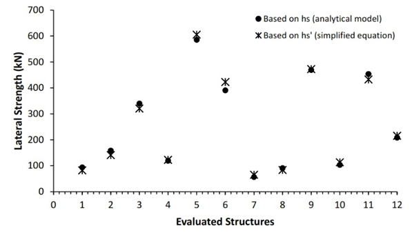
Fig. 4. Comparison of masonry infill lateral strength-based contact length hs and hs’
The correlation between lateral strength and displacement, as an indication of the seismic performance of the assessed structures based on the strut model, is illustrated in a bilinear model as depicted in Fig. 5.
3.3 Pushover method for verification
To validate the analytical model, the pushover method was employed using the SeismoStruct software to assess the structure's lateral strength and deformation. This method involved modeling columns, beams, and masonry walls using non-linear analytical techniques (pushover), employing the Mander model for concrete materials, the Menegotto-Pinto model for steel, and incorporating inelastic forces for frames [23]. The x, y, and z global axes, representing length, depth, and height respectively, were utilized to delineate the inelasticity of the materials within SeismoStruct. The brick masonry infill was modeled using empirical parameters and techniques to achieve results closely aligned with parameter testing confirmed by research findings [24]. Table 4 shows the geometric and mechanical parameters related with brick masonry infills.
Table 4. Parameters of brick masonry infills for pushover evaluation
|
No. |
Parameters |
Structure models |
|||||||||||
|
1 |
2 |
3 |
4 |
5 |
6 |
7 |
8 |
9 |
10 |
11 |
12 |
||
|
1 |
$f_{m\theta}$ (kN/m²) |
5328 |
590 |
3483 |
746 |
5999 |
4020 |
951 |
1567 |
4791 |
629 |
1260 |
903 |
|
2 |
$f_t$ (kN/m²) |
0.00 |
0.00 |
0.00 |
0.00 |
0.00 |
0.00 |
0.00 |
0.00 |
0.00 |
0.00 |
0.00 |
0.00 |
|
3 |
$\varepsilon_m$ |
0.00 |
0.00 |
0.00 |
0.00 |
0.00 |
0.00 |
0.00 |
0.00 |
0.00 |
0.00 |
0.00 |
0.00 |
|
4 |
$\varepsilon_u$ |
0.04 |
0.04 |
0.04 |
0.04 |
0.04 |
0.04 |
0.04 |
0.04 |
0.04 |
0.04 |
0.04 |
0.04 |
|
5 |
|
0.00 |
0.00 |
0.00 |
0.00 |
0.00 |
0.00 |
0.00 |
0.00 |
0.00 |
0.00 |
0.00 |
0.00 |
|
6 |
|
0.00 |
0.00 |
0.00 |
0.00 |
0.00 |
0.00 |
0.00 |
0.00 |
0.00 |
0.00 |
0.00 |
0.00 |
|
7 |
|
0.01 |
0.01 |
0.01 |
0.01 |
0.01 |
0.01 |
0.01 |
0.01 |
0.01 |
0.01 |
0.01 |
0.01 |
|
8 |
$\gamma_{un}$ |
1.50 |
1.50 |
1.50 |
1.50 |
1.50 |
1.50 |
1.50 |
1.50 |
1.50 |
1.50 |
1.50 |
1.50 |
|
9 |
$\alpha_{re}$ |
0.20 |
0.20 |
0.20 |
0.20 |
0.20 |
0.20 |
0.20 |
0.20 |
0.20 |
0.20 |
0.20 |
0.20 |
|
10 |
$\alpha_{ch}$ |
0.70 |
0.70 |
0.70 |
0.70 |
0.70 |
0.70 |
0.70 |
0.70 |
0.70 |
0.70 |
0.70 |
0.70 |
|
11 |
$\beta_a$ |
1.50 |
1.50 |
1.50 |
1.50 |
1.50 |
1.50 |
1.50 |
1.50 |
1.50 |
1.50 |
1.50 |
1.50 |
|
12 |
$\beta_{ch}$ |
0.90 |
0.90 |
0.90 |
0.90 |
0.90 |
0.90 |
0.90 |
0.90 |
0.90 |
0.90 |
0.90 |
0.90 |
|
13 |
$\gamma_{plu}$ |
1.00 |
1.00 |
1.00 |
1.00 |
1.00 |
1.00 |
1.00 |
1.00 |
1.00 |
1.00 |
1.00 |
1.00 |
|
14 |
$\gamma_{plr}$ |
1.10 |
1.10 |
1.10 |
1.10 |
1.10 |
1.10 |
1.10 |
1.10 |
1.10 |
1.10 |
1.10 |
1.10 |
|
15 |
$ex_1$ |
3.00 |
3.00 |
3.00 |
3.00 |
3.00 |
3.00 |
3.00 |
3.00 |
3.00 |
3.00 |
3.00 |
3.00 |
|
16 |
$ex_2$ |
1.00 |
1.00 |
1.00 |
1.00 |
1.00 |
1.00 |
1.00 |
1.00 |
1.00 |
1.00 |
1.00 |
1.00 |
|
17 |
$\tau_0$ (kN/m²) |
390 |
120 |
308 |
92 |
525 |
426 |
113 |
179 |
467 |
50 |
105 |
74 |
|
18 |
|
0.62 |
0.62 |
0.62 |
0.62 |
0.62 |
0.62 |
0.62 |
0.62 |
0.62 |
0.62 |
0.62 |
0.62 |
|
19 |
$\tau_{max}$ (kN/m²) |
5037 |
1078 |
3560 |
980 |
6168 |
4738 |
1266 |
2031 |
5298 |
594 |
1189 |
838 |
|
20 |
|
1.43 |
1.43 |
1.43 |
1.43 |
1.43 |
1.43 |
1.43 |
1.43 |
1.43 |
1.43 |
1.43 |
1.43 |
|
21 |
t (m) |
0.04 |
0.12 |
0.09 |
0.12 |
0.12 |
0.09 |
0.08 |
0.06 |
0.09 |
0.20 |
0.20 |
0.15 |
|
22 |
Op (%) |
5.00 |
5.00 |
5.00 |
5.00 |
5.00 |
5.00 |
5.00 |
5.00 |
5.00 |
5.00 |
5.00 |
5.00 |
|
23 |
$A_1$ (m²) |
0.01 |
0.06 |
0.06 |
0.07 |
0.07 |
0.05 |
0.03 |
0.03 |
0.06 |
0.13 |
0.24 |
0.17 |
|
24 |
$A_2$ (%) |
70.00 |
70.00 |
70.00 |
70.00 |
70.00 |
70.00 |
70.00 |
70.00 |
70.00 |
70.00 |
70.00 |
70.00 |
|
25 |
$h_z$ (%) |
27.54 |
26.61 |
25.59 |
25.96 |
25.96 |
25.90 |
27.12 |
27.07 |
25.78 |
25.53 |
24.74 |
24.78 |
|
26 |
|
13.89 |
8.33 |
13.64 |
8.70 |
11.11 |
8.34 |
7.59 |
10.42 |
8.35 |
7.14 |
10.00 |
3.18 |
|
27 |
$y_o$ (%) |
26.67 |
20.00 |
22.22 |
19.23 |
15.38 |
17.08 |
14.44 |
23.26 |
16.10 |
12.31 |
15.00 |
13.89 |
|
28 |
Ps (%) |
20.00 |
20.00 |
20.00 |
20.00 |
20.00 |
20.00 |
20.00 |
20.00 |
20.00 |
20.00 |
20.00 |
20.00 |
|
29 |
Sw (kN/m³) |
17.00 |
17.00 |
17.00 |
17.00 |
17.00 |
17.00 |
17.00 |
17.00 |
17.00 |
17.00 |
17.00 |
17.00 |
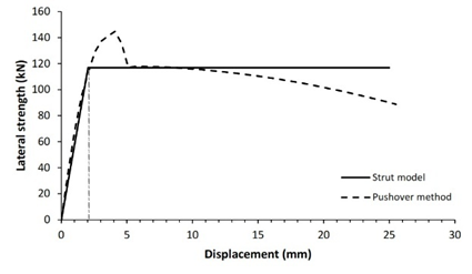
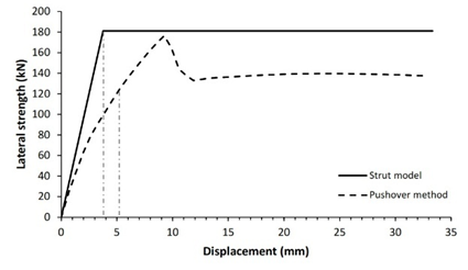
3.4 Verification of analytical method
The verification technique involves comparing the lateral strength of infilled frame structures as studied by the diagonal strut method to that determined by the pushover method. Fig. 5 shows comparison curves of seismic capacity calculated using the diagonal strut and pushover approaches.
|
(a) Structure model 1 |
(b) Structure model 2 |
|
(c) Structure model 3 |
(d) Structure model 4 |
|
(e) Structure model 5 |
(f) Structure model 6 |
|
(g) Structure model 7 |
(h) Structure model 8 |
|
(i) Structure model 9 |
(j) Structure model 10 |
|
(k) Structure model 11 |
(l) Structure model 12 |
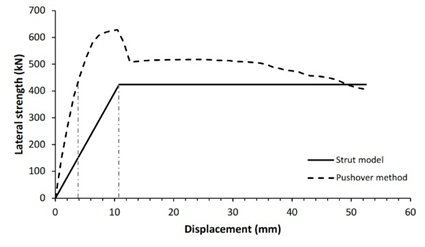
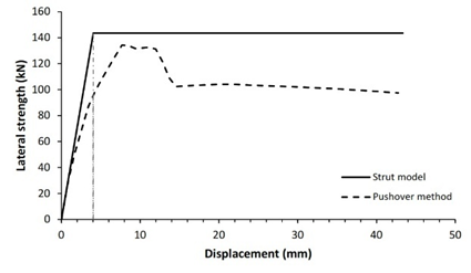
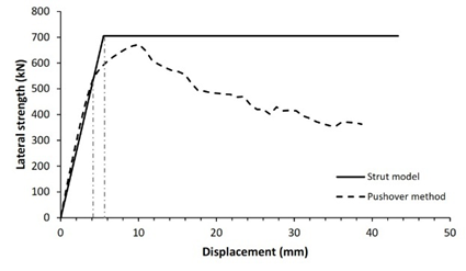
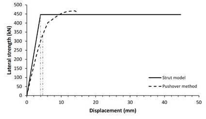
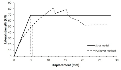
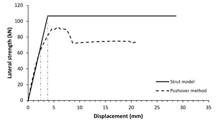
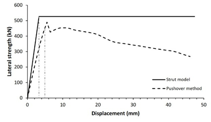
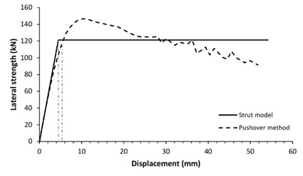
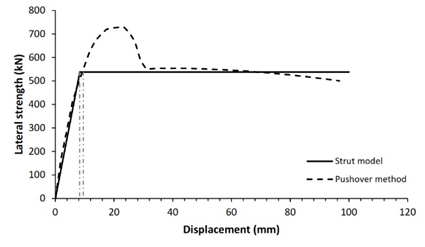
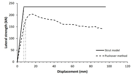
Validation of both processes reveals that 83.3% of the 12 structure models have nearly identical lateral strength for both pushover and analytical approaches, with a variance of less than 20%, as shown in Table 5. Two structure models, specifically models 3 and 11, demonstrated lateral strength variations of more than 20%. It is heavily influenced by the span-length-to-wall-height ratio. Five of structure models had a tiny span ratio difference between 1.2 and 1.3 while the others have a ratio between 1.4 and 2.4. This analysis shows that the technique is preferable and more suitable for structures with a span ratio of 1.2 to 2.4. For lower span ratios, the response of RC frame structures with masonry infills is governed by shear-dominated behavior rather than diagonal compression mechanism assumed in simplified strut model, leading to nonuniform frame-infill contact condition and potentially inaccurate lateral strength prediction. Overall, this demonstrates that the seismic performance of reinforced concrete frame structures with masonry infill can be effectively evaluated using a simplified equation for the infill-column contact height within the diagonal strut method, providing substantial computational time saving while maintaining satisfactory accuracy.
Table 5. Verification of lateral strength-based strut model with pushover methods
|
Model Structure |
Analytical model |
Pushover method |
Validation of lateral strength |
||
|
Lateral strength of infilled frame (kN) |
Displacement at yield (mm) |
Lateral strength of infilled frame (kN) |
Displacement at yield (mm) |
||
|
1 |
116.9 |
2.0 |
144.3 |
2.0 |
18.9% |
|
2 |
181.1 |
3.8 |
176.4 |
5.1 |
2.7% |
|
3 |
424.2 |
10.8 |
628.3 |
4.6 |
32.5% |
|
4 |
143.5 |
4.1 |
134.2 |
4.1 |
6.9% |
|
5 |
705.6 |
5.5 |
693.6 |
3.9 |
1.7% |
|
6 |
446.6 |
4.0 |
465.9 |
5.2 |
4.2% |
|
7 |
69.0 |
4.7 |
80.8 |
5.5 |
14.5% |
|
8 |
106.6 |
3.8 |
122.5 |
3.1 |
12.9% |
|
9 |
52.7 |
3.3 |
488.8 |
4.8 |
7.7% |
|
10 |
121.2 |
4.5 |
146.4 |
5.3 |
17.2% |
|
11 |
538.0 |
8.3 |
730.1 |
9.0 |
26.3% |
|
12 |
235.0 |
7.0 |
203.6 |
8.8 |
15.4% |
4 Conclusions
This study uses the diagonal strut method to examine the seismic capabilities of RC frame structures with masonry infills. After evaluating twelve structure models, it was discovered that the infill-column contact height (hs) and the column height (L) were directly related for predicting the strut width. The proximity of the infill-column contact height to the column height allows for the use of linear regression analysis, resulting in an equation that indicates the infill-column contact height is approximately one-quarter of the column height.
The lateral strength of infilled frame structures as investigated by the diagonal strut method was compared to that determined by the pushover method to verify the analytical method. Consequently, both processes demonstrate that 83.3% of the 12 structure models maintain nearly identical lateral strength for both analytical and pushover approaches, with a variance of less than 20%. This clarifies the assessment of the seismic capability of reinforced concrete frame structures with masonry infill by a simplified equation for infill column contact height in the diagonal support method.
Acknowledgements
The authors declare that no funds, grants, or other support were received during the preparation of this research.
References
- Mehrabi, A. B., Shing, P. B., Schuller, M. P., and Noland, J. L. (1996). Experimental evaluation of masonry infilled RC frame. Journal Structure Engineering, 122(3), 228-23, https://doi.org/10.1061/(ASCE)0733-9445(1996)122:3(228).
- Chaker, A. A., and Cherifati, A. (1999). Influence of masonry infill panels on the vibration and stiffness characteristics of R/C frame buildings. Earthquake Engineering and Structural Dynamics, 28(9), 1061-1065, https://doi.org/10.1002/(SICI)1096-9845(199909)28:9<1061::AID-EQE856>3.0.CO;2-3.
- Maidiawati, Sanada,Y., Konishi, D., and Tanjung, J. (2011). Seismic performance of nonstructural brick walls used in Indonesian R/C buildings. Journal of Asian Architecture and Building Engineering, 10(1), 203-210, DOI: 10.3130/jaabe.10.203.
- Maidiawati, and Sanada, Y. (2017). R/C Frame-infill interaction model and its application to Indonesian buildings. Earthquake Engineering and Structural Dynamics, 46(2), 221-241, DOI: 10.1002/eqe.2787.
- Holmes, M. (1961). Steel Frame with brickwork and concrete infilling. In Proceedings of the Institution of Civil Engineers (pp. 473-478), Emerald Publishing https://doi.org/10.1680/iicep.1961.11305.
- Smith, B. S., and C. Carter, C. (1969). Method of analysis for infilled frames. In Proceedings of the Institution of Civil Engineers (pp. 31-48), https://doi.org/10.1680/iicep.1969.7290.
- Mainstone, R. J., and Weeks, G. A. (1970). The influence of a bounding frame on the racking stiffnesses and strengths of brick walls. In Building Research Establishment (pp. 165-171).
- Mainstone, R. J. (1971). On the strengths of infilled frames. In Proceedings of the Institution of Civil Engineers, 49(2), 230, https://doi.org/10.1680/iicep.1971.6267.
- Leuchars, J. M., Scrivener,J. C. (1976). Masonry infill panels subjected to cyclic in-plane loading. In Bulletin of the New Zealand Society for Earthquake Engineering, 9(2), pp. 122–131, https://doi.org/10.5459/bnzsee.9.2.122-131
- Paulay, T. and Pristley, M. J. N. (1992). Seismic design of reinforced concrete and masonry buildings. John Wiley & Sons, DOI: 10.1002/9780470172841 .
- Suku, Y. L., and Radja, V. M. (2025). Analysis study of reinforced concrete frame structures with infill walls due to lateral loads using the equivalent diagonal strut and finite element method. Journal of Applied Engineering Science, 23(1), 37-44, https://doi.org/10.5937/jaes0-50941.
- Maidiawati, Tanjung, J., Hayati, Y., Agus, and Medriosa, H. (2019). Experimental investigation of seismic performance of reinforced brick masonry infilled reinforced concrete frames with a central opening. International Journal of Geomate, 16(57), 35-41, https://doi.org/10.21660/2019.57.4592.
- Dautaj, A. D., Muriqi, A., Kraniqi, C., and Shatri, B. (2019). Shear resistance of masonry panel in infilled RC frames. International Journal of Advanced Structural Engineering, 11, pp. 165-177.
- Kim, M. and Yu, E. (2021). Experimental study on lateral-load-resisting capacity of masonry-infilled reinforced concrete frames. Applied Sciences, 11(21), 9950, https://doi.org/10.3390/app11219950.
- Bergami, A. V., and Nuti, C. (2015). Experimental tests and global modeling of masonry infilled frames. Earthquakes and Structures, 9(2), 281-303, https://doi.org/10.12989/eas.2015.9.2.281.
- Penava,D., Sarhosis, V. Kozar, I and Guljaz, I. (2018). Contribution of RC columns and masonry wall to the shear resistance of masonry infilled rc frames containing different in size window and door openings. Engineering Structures,172, 105-130, https://doi.org/10.1016/j.engstruct.2018.06.007.
- Stavridis, A and Shing, P. B. (2010). Finite-Element modeling of nonlinear behavior of masonry-infilled RC frames. Journal Of Structural Engineering,136(3), https://doi.org/10.1061/(ASCE)ST.1943-541X.116.
- Soulis, V. J. (2018). Micro and macro-modeling techniques for the simulation of the masonry infilled R/C Frames under earthquake type loading. European Journal of Engineering Research and Science, 3(8), 16-25, https://doi.org/10.24018/ejeng.2018.3.8.847.
- Dewobroto, W. (2005). Analisa inelastis portal - dinding pengisi dengan equivalent diagonal strut. Jurnal Teknik Sipil ITB, 2(4), 229-240, https://doi.org/10.5614/jts.2005.12.4.1.
- Braz-Cesar, M. T., Oliveira, D. V., and Barros,R. C. (2008). Numerical validation of the experimental cyclic response of RC frames. (pp. 267-291). in European Science Foundation (ESF), Strasbourg.
- Cai, G., and Su, Q. (2017). Effect of infills on seismic performance of reinforced concrete frame structures – a full scale experimental study. Journal of Earthquake Engineering, 23(29), https://doi.org/10.1080/13632469.2017.1387194.
- Bahreini, V., Mahdi, T. and Najafizadeh, M. M. (2017). Evaluation of brick infill walls under in-plane and out-of-plane loading. Journal of Vibroengineering, 19(1), 394-408, https://doi.org/10.21595/jve.2016.17259.
- Seismosoft (2024). Seismostruct 2024 – A computer program for static and dynamic nonlinear analysis of framed structures, https://www.seismosoft.com
- Crisafulli, F. J. (1997). Seismic behaviour of reinforced concrete structures with masonry infills. In Engineering Library Thesis, Department of Civil Engineering, University of Canterbury, Christchurch, New Zealand, 1997.
Conflict of Interest Statement
The authors declare no conflict of interest.
Author Contributions
Data Availability Statement
There is no dataset associated with the study or data is not shared.
Supplementary Materials
There are no supplementary materials to include.