Volume 23 article 1306 pages: 715-723
Received: Jun 15, 2025 Accepted: Oct 20, 2025 Available Online: Nov 26, 2025 Published: Dec 15, 2025
DOI: 10.5937/jaes0-59523
STUDY OF THE STRESS-STRAIN STATE OF BUSBAR PUNCHING TOOLS RESTORED BY VARIOUS METHODS
Abstract
The aim of this study is a comparative analysis of the stress–strain state of busbar punching tools after restoration using different methods. An overview of existing methods for restoring punches and dies was conducted. The analysis showed that each method has its own advantages and limitations. To address this issue, two restoration methods for the busbar punching tool are proposed: hardfacing of worn and damaged surfaces, and replacement of the working part with an insert made of carbon steel. A numerical simulation using the ANSYS software package was carried out to investigate the stress–strain state of busbar punching tools restored by two proposed methods. The simulation focused on determining the stresses in the working zones of the tool, deformations, and the distribution of contact forces. The results made it possible to identify critically loaded areas of the tool design and evaluate the effectiveness of the proposed restoration and modernization methods. The research, the results of which are presented in this article, is funded by the Committee on Science of the Ministry of Science and Higher Education of the Republic of Kazakhstan (grant № AP19578884 "Increasing wear resistance and improving the design of the tool of the busbar punching machine").
Highlights
- Premature wear of transformer busbar punching tools was systematically analyzed;
- Two restoration techniques: hardfacing and carbon steel inserts were developed;
- Numerical simulation in ANSYS verified stress reduction and enhanced durability.
Nomenclature
H12M – high-alloy hot-work tool steel containing chromium and molybdenum;
$\varepsilon_f $ – equivalent plastic strain;
$\sigma_H^\ast$ – stress triaxiality;
T* – dimensionless temperature;
D₁, D₂, D₃ – parameters describing the influence of stress triaxiality on the failure strain;
D₄ – parameter describing the influence of strain rate on the failure strain;
D₅ – parameter describing the influence of temperature on the failure strain.
Keywords
Content
1 Introduction
In the current context, improving the quality of stamped products is not only an objective necessity driven by the level of scientific and technological progress, but also a critical factor in ensuring the competitiveness of manufacturing enterprises. On one hand, there is a growing demand for higher precision of geometric parameters and enhanced functionality of components, which is reflected in technological processes through the introduction of new structural materials and strengthened surface layers. On the other hand, there is a significant increase in the requirements for sheet metal stamping tooling, including performance indicators, cost-effectiveness, and operational reliability. These demands are driven by intensifying competition amid the rapid advancement of technology.
One of the technologies widely used in mechanical and electromechanical engineering plants is the punching of holes in transformer busbars using busbar punching tools. This process is carried out with the use of busbar punching press machines [1, 2].
The conducted research has shown that there is a significant issue of premature wear of busbar punching tools, as well as challenges associated with their restoration [3, 4, 5].
Based on operating conditions, the punch and die are classified as heavily loaded tools, as they come into direct contact with the pressed metal. The punching process takes place under high temperatures, pressures, and intense friction. The primary cause of severe tool wear is overheating, which leads to a decrease in strength and, consequently, to deformation. In particular, die wear occurs when the temperature during operation exceeds the tempering temperature, potentially resulting in plastic deformation.
The operating conditions of the tool have a substantial impact on its durability. In most cases, the punching process is not smooth – impact loads exerted on the tool require materials with high impact toughness, which is often difficult to combine with high hardness. Impact loading reduces the service life of punching tools [7,8,9]. Abrupt pressure release, which can be avoided, may lead to tool breakage. Prolonged exposure of the tool to high-temperature zones (approximately 850°C for copper and up to 1100°C for steel) significantly reduces its durability.
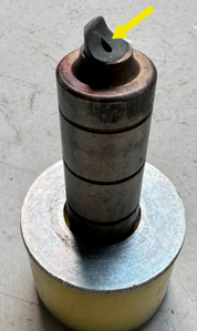
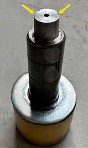
Figure 1 shows worn-out busbar punching tools.
 |
 |
| a) | b) |
Fig. 1. Worn busbar punching tools
To clarify the causes of damage in the body of the busbar punching tool, a finite element analysis was carried out using the Deform 3D software package [6, 7].
The simulation results in Deform 3D showed that compressive stresses dominate at the initial stages of the process, reaching values up to 200 MPa. During deformation, as the material moves toward the die walls, the stresses remain predominantly compressive. It was determined that the increase in tensile stresses and deformation occurs precisely in the areas where wear or failure is observed in actual production.
This state of the problem highlights the need to develop effective methods for restoring the worn working surfaces of busbar punching tools. Special attention must be paid to ensuring the wear resistance of the tool's working part, which is subjected to impact loads and high pressure in the contact zone with the workpiece.
Under conditions of intensive operation, such tools are subjected to a complex range of effects – from high thermomechanical loads to abrasive wear and fatigue failure. Damage may vary in nature, from chipping and wear of cutting edges to extensive cracking and deformation [10]. Given the high manufacturing costs, complex geometry, and the need to ensure machining accuracy, the restoration of damaged components often becomes a more cost-effective alternative to complete replacement [8, 15].
Recent studies confirm the effectiveness of various restoration methods, with the choice depending on both the type of damage and the tool material. The most widely used techniques include manual arc welding and gas tungsten arc welding (GTAW/TIG), due to the availability of equipment and the versatility of the processes [13,15]. These methods allow for the restoration of large tool areas and the use of various filler materials. However, the high heat input associated with these processes can alter the microstructure of the base metal, induce residual stresses, and even cause new cracks, especially when repairing hardened and tempered steels [15]. In such cases, the quality of the restored area strongly depends on the operator's skill and the correct selection of welding parameters.
At the same time, advanced technologies such as laser welding and laser cladding are actively being developed. These methods enable localized restoration with minimal heat-affected zones. The use of pulsed Nd:YAG lasers has demonstrated the ability to produce high-quality welds without the need for preheating, which is particularly important for tool steels such as AISI D2 [9]. Pulse shape control and precise parameter adjustment help prevent cracking and deformation; however, implementation of these methods requires complex and expensive equipment, as well as high precision in selecting technological parameters.
In addition, laser chemical-thermal treatment and laser alloying offer the possibility of modifying the working surfaces of tools, enhancing their wear resistance and dynamic strength without the need to replace the base material [10]. The use of carbon steels with localized laser hardening makes it possible to substitute more expensive high-alloy materials while maintaining the required performance characteristics. However, these methods generally do not eliminate deep damage and are unsuitable in the presence of internal cracks or structural defects.
A promising direction is the application of additive manufacturing technologies, such as Directed Energy Deposition (DED), which enable the creation of heterogeneous, multilayer structures. The combination of wear-resistant and tough layers makes it possible to achieve high impact toughness, strength, and hardness while maintaining the overall reliability of the tool [11]. This semi-additive approach has shown significant improvements in mechanical properties compared to conventional materials. However, the high equipment requirements, complexity of controlling transition zones, and elevated costs limit the widespread adoption of such methods in mass production environments.
Automated restoration systems are gaining additional relevance, especially those incorporating numerical modeling of welding and thermal effects. The use of advanced simulation software enables prediction of temperature and stress distributions, thereby minimizing the risk of overheating and structural alterations [14]. Nevertheless, these approaches demand substantial resources, qualified engineering support, and integration into production workflows at the level of systemic process management.
Special attention is given to the fatigue strength of restored materials, particularly in the case of laser cladding. Although defects in the cladded zone can reduce mechanical performance, properly selected process parameters can enhance fatigue strength even beyond that of non-restored specimens [12, 18]. However, a thorough assessment of the metallurgical characteristics and microstructure of the deposited layers is required.
Thus, the analysis of existing restoration methods shows that each has its own advantages and limitations, and their effectiveness largely depends on the type of damage, accuracy requirements, and available resources. Modern technologies offer high precision and minimal thermal deformation, but they are associated with significant costs for equipment and personnel training. Traditional methods remain relevant for restoring large tool areas but require strict process control and subsequent finishing operations. The most rational approach appears to be the integration of different methods tailored to specific tasks, which allows for optimizing the repair process, extending tool life, and reducing production costs.
2 Materials and methods
Within the framework of these objectives, the Department of "Technological Equipment, Mechanical Engineering, and Standardization" is carrying out a scientific project funded by the Committee of Science of the Ministry of Science and Higher Education of the Republic of Kazakhstan (grant AP19578884 "Increasing wear resistance and improving the design of the tool of the busbar punching machine"). The project is focused on the restoration and improvement of wear resistance in busbar punching tools. Particular attention is paid to identifying design and technological solutions capable of addressing the shortcomings identified in the literature.
As a result of the research, two restoration methods for worn busbar punching tools were proposed, along with the development of a new tool design that provides enhanced strength, maintainability, and operational durability.
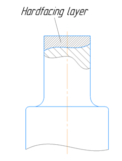
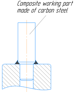
Figure 2 shows the proposed methods for restoring busbar punching tools.
 |
 |
| a) | b) |
Fig. 2. Methods for restoring busbar punching tools: a – restoration by hardfacing; b – composite tool design
Figure 3 shows the hole punching process using a busbar punching tool.
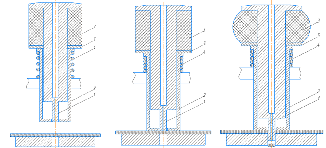
| a) | b) | c) |
Fig. 3. Hole punching process using a busbar punching tool: a – tool setup; b – beginning of the hole punching process; c – hole punching process; 1 – punch; 2 – punch holder; 3 – buffer; 4 – spring; 5 – washer
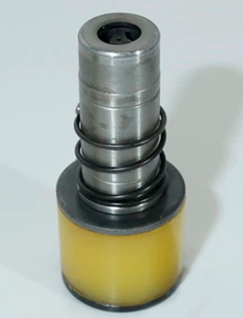
Figure 4 shows the exploded view of the busbar punching tool.
 |
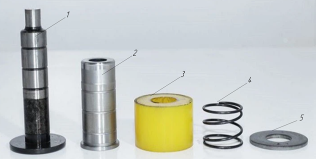 |
| a) | b) |
Fig. 4. Design of the busbar punching tool: a – assembled tool; b – exploded view: 1 – punch; 2 – punch holder; 3 – buffer; 4 – spring; 5 – washer
One of the research directions involves the restoration of worn working surfaces of the tool by means of hardfacing (Figure 2a). As the hardfacing material, ESAB OK Tubrodur 35GM wire was used, known for its high wear resistance and hardness. During the experimental work, optimal hardfacing parameters were determined to ensure the required hardness and strength of the restored layer. The selection of process parameters was carried out with consideration of the operational requirements for the tool, including resistance to contact wear and impact loads.
In addition, an alternative restoration method is being developed at the department, based on replacing the worn section of the busbar punching tool’s working surface with an insert made of carbon steel. Analysis showed that the majority of failures occur in the transition zone between the working part and the guide. Accordingly, a design was proposed in which the working part is manufactured separately and joined to the guide section by welding. This approach allows for reduced restoration costs while maintaining the necessary strength and performance characteristics. The structural solution of this method is shown in Figure 2b.
2.1 Study of the stress-strain state of busbar punching tools
To study the stress-strain state of the busbar punching tool, a numerical simulation methodology was applied using the ANSYS software package. ANSYS is a leading tool for finite element analysis (FEA), enabling detailed calculations of mechanical, thermal, electrical, and other processes in engineering systems. To evaluate the propagation of shock waves, large deformations, and material failure, the Static Structural and Explicit Dynamics modules were used.
The main objective of the simulation was to identify the most highly loaded areas of the punch during the punching process. Identifying these zones is critical for assessing tool durability, predicting potential failure or plastic deformation points, and further optimizing the tool design or selecting appropriate materials.
Figure 5 shows the simulation model of the die in interaction with the punch and the press workpiece.
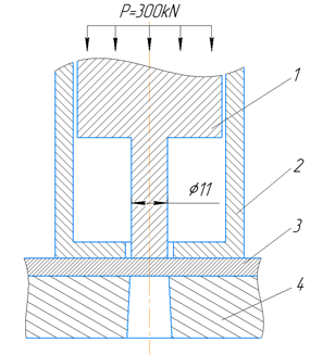
Fig. 5. Simulation model of the die interacting with the punch and the press workpiece: 1 – punch; 2 – punch holder; 3 – plate (workpiece); 4 – die
The stress-strain state analysis was carried out in stages, taking into account various tool design configurations:
1) Initial model – the tool entirely made of tool steel grade H12M, without the use of any enhancement or restoration methods.
2) Model restored by hardfacing – the tool whose working part was restored using Tubrodur hardfacing material.
3) Composite model – the tool with the worn part of the punch replaced by a carbon steel insert fixed into the tool body.
In the ANSYS environment, contact interactions were taken into account at the punch–workpiece and workpiece–die interfaces. The punching force was set as P = 300 kN.
To describe the complex elastic-plastic behavior of materials under high strain rates and thermal effects, the Johnson-Cook material model was used. This model also allows for numerical prediction of the onset of material failure, which is critical for optimizing the punching process, forecasting hole quality, and evaluating loads on the punch.
Copper fails via a ductile mechanism, primarily governed by the accumulation of plastic strain. The equivalent plastic strain at failure ($\varepsilon_f $) is defined as:
| $$\varepsilon_f = \left[ D_1 + D_2 e^{D_3 \sigma_H^{*}} \right] \left( 1 + D_4 \left( \ln \dot{\varepsilon}^{*} \right) \right) \left( 1 + D_5 T^{*} \right)$$ | (1) |
where $\sigma_H^{*} = \frac{\sigma_H}{\sigma_{eq}}$ is the stress triaxiality, defined as the ratio of the mean hydrostatic stress (σH) to the equivalent von Mises stress (σeq). This parameter is critical because it characterizes the nature of the stress state and significantly influences ductility prior to failure: the higher the tensile triaxiality, the lower the strain to failure;
$\dot{\varepsilon}^{*}$ is the dimensionless strain rate;
T* is the dimensionless temperature;
D₁, D₂, D₃ – parameters describing the influence of stress triaxiality on the failure strain. For ductile materials such as copper, these parameters indicate that under high tensile triaxialities, the strain to failure decreases;
D₄ – parameter describing the influence of strain rate on the failure strain;
D₅ – parameter describing the influence of temperature on the failure strain. For copper, ductility typically increases with temperature, so D₅ is generally positive.
Failure occurs when the accumulated damage parameter D reaches a critical value (usually 1.0).
| $D = \sum \frac{\Delta \varepsilon_p}{\varepsilon_f}$ | (2) |
where Δϵp is the increment of equivalent plastic strain obtained at each calculation step, and ϵf is the current value of the failure strain, calculated using the above-mentioned formula under the current conditions.
A finite element model of the investigated object was developed in the simulation environment (Figure 6).
|
|
||
|
a) |
b) |
с) |
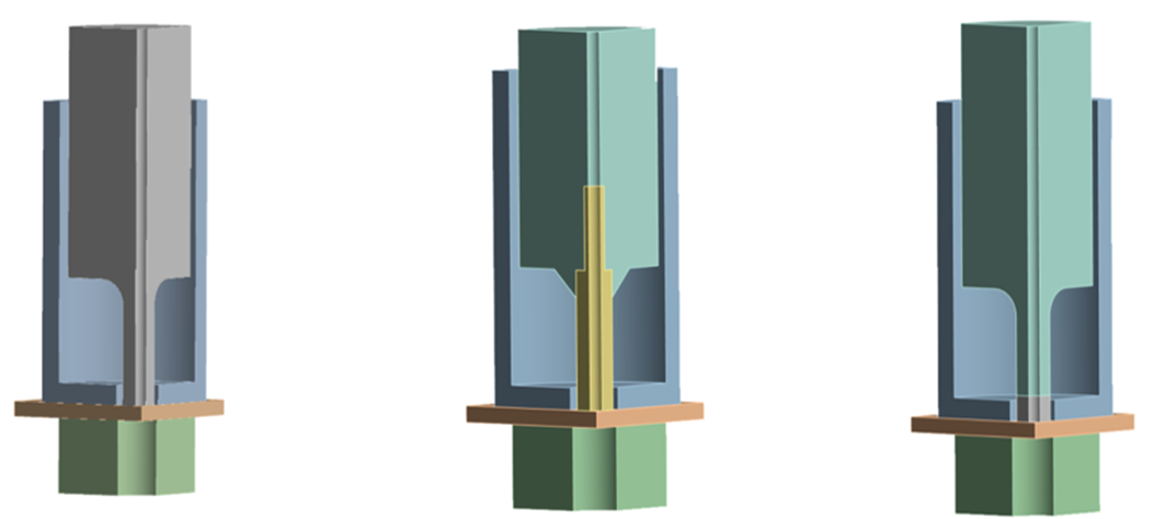
Fig. 6. Finite element model: a – initial model; b – assembled (composite) model; c – model restored by hardfacing (welding deposition) method
To improve computational efficiency and reduce calculation time, a quarter-symmetry model of the full geometry was used. This approach is a standard practice in finite element analysis (FEA) when both geometry and loading conditions exhibit symmetry. The use of a quarter model significantly reduces the number of finite elements, which in turn decreases computation time and lowers the demand on computational resources—without compromising the accuracy of results for symmetric problems. The obtained results from the quarter model can be extrapolated to represent the behavior of the full model.
3 Results and discussion
At each stage of the simulation, stress fields, strain distributions, and contact force distributions in the working zones of the tool were determined. The analysis results made it possible to identify critically loaded regions of the structure, as well as to evaluate the effectiveness of the proposed restoration and modernization methods.
Figure 7 shows the stress–strain state of the tool made of H12М steel.
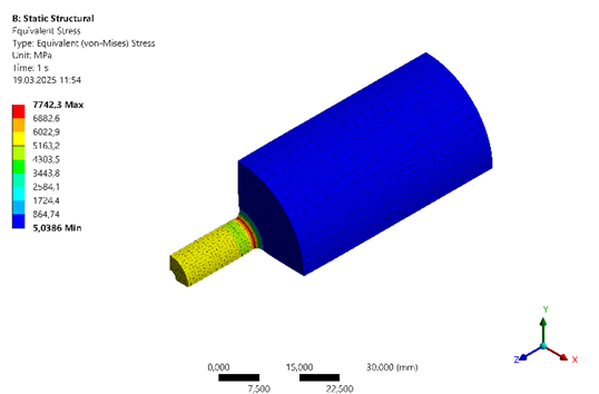
Fig. 7. Stress-strain state of the tool made of H12М steel
The color distribution on the model visually represents the stress levels in various zones of the tool. The finite element simulation enabled the precise identification of the most critically loaded areas. The analysis revealed that the highest stress concentrations occur at the cutting edge of the punch and in the transition area from the working part to the guiding section, which is typical for cutting and punching tools operating under impact and contact loads.
The peak stress reached 7742.3 MPa, which significantly exceeds the tensile strength limit of H12М tool steel, typically ranging from 2500 to 3000 MPa after optimal heat treatment. Such a high value indicates a very high risk of failure: either plastic deformation or, more likely, brittle fracture may occur during the first punching cycle or after only a few cycles. This confirms the need for structural improvements and the implementation of restorative technologies.
To address this issue, two methods were proposed and investigated for improving tool durability:
- rebuilding the working surface by hardfacing with a wear-resistant alloy;
- implementing a modular design, replacing the worn section with a carbon steel insert.
Both approaches were further analyzed using the ANSYS simulation environment.
Figure 8 shows the stress-strain state of the tool restored by hardfacing.
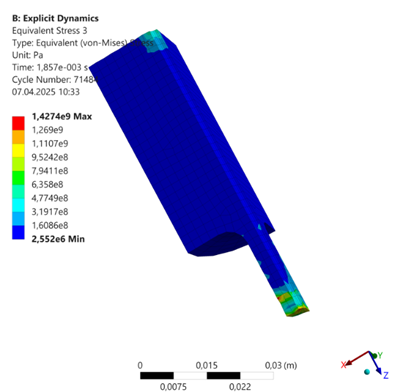
Fig. 8. Stress-strain state of the tool restored by hardfacing
The finite element simulation results, performed using explicit dynamic analysis, show the distribution of von Mises equivalent stresses in the working tool restored by hardfacing with Tubrodur wear-resistant flux-cored wire. The image reveals peak stress values up to 1427.4 MPa, concentrated along the cutting edge of the tool, indicating extremely high loading in this area during the punching process (see Figure 8).
The simulation confirms that both the tool body and the deposited hardfacing layer can withstand the calculated operational loads without immediate failure according to the von Mises failure criterion.
Figure 9 presents the stress-strain state of the composite (modular) tool.
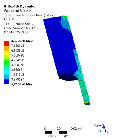
Fig. 9. Stress-strain state of the composite tool
The highest stress levels, indicated in red on the color scale, are concentrated exclusively along the cutting edge of the tool. As the distance from the cutting edge increases into the body of the tool, the stress values rapidly decrease, transitioning from maximum to significantly lower levels. For the working part of the tool made from carbon steel, a value of 847.27 MPa is within the acceptable range. Carbon tool steels (such as U8, U10, U12) after proper heat treatment (quenching and tempering) can exhibit yield strengths ranging from 600 to 1000 MPa, and ultimate tensile strengths from 1000 to 1200 MPa or more. Thus, the obtained maximum stress is likely within the allowable strength limits of high-strength tool-grade carbon steel. This indicates that, under the given load level, the cutting edge of the tool is not expected to fail immediately and is capable of withstanding such stresses without undergoing significant plastic deformation or brittle fracture.
4 Conclusions
The conducted research has shown that press machines for punching holes in transformer busbars are widely used in mechanical engineering and electrical manufacturing industries. It was identified that there is a problem of premature wear of busbar punching tools, as well as difficulties in their restoration due to the absence of an established technological process for repair and recovery. To address this issue, two restoration methods have been proposed: hardfacing (weld overlay) and replacement of worn or broken tool surfaces with a carbon steel insert in the working part of the tool.
Using numerical simulation in the ANSYS software suite, the stress-strain state of busbar punching tools restored by the proposed methods was studied. The simulation assessed the stresses in working zones, deformations, and contact force distributions. The results made it possible to identify critical stress concentrations in the tool's structure and evaluate the effectiveness of the proposed repair and modernization techniques.
It was revealed that the most highly stressed area of the punch is its cutting edge and the transition zone from the working section to the guide section with a larger diameter. The peak stress value reached 7742.3 MPa, which is unacceptable for H12M tool steel. This condition highlights the need for further experimental and analytical studies, as well as, if necessary, the application of additional hardening methods.
Simulation of the tool restored using hardfacing with wear-resistant ESAB OK Tubrodur 35GM powder wire revealed that the stress concentration at the cutting edge reaches 1427.4 MPa. Under these conditions, the tool and deposited layer are able to withstand the operational loads without immediate failure according to the von Mises criterion.
In the case of the tool restored by replacing the working part with a carbon steel insert, simulation showed that the maximum stress in the working zone reached 847.27 MPa, which is within the allowable strength limits for high-strength tool-grade carbon steel.
The results of the finite element analysis confirm the feasibility of the proposed restoration methods. Further experimental validation of the busbar punching tools restored by hardfacing and insertion of a carbon steel component is required under both laboratory and industrial conditions.
Acknowledgements
The research, the results of which are presented in this article, is funded by the Committee on Science of the Ministry of Science and Higher Education of the Republic of Kazakhstan (grant AP19578884 "Increasing wear resistance and improving the design of the tool of the busbar punching machine").
References
- Kargin, V., Kargin, B., Aryshensky, E. (2012). Technology of profile pressing from light alloys: Methodical guidelines. Samara: Publishing House of SGAU, 54
- Shcherba, V. (2001). Pressing of aluminum alloys. Moscow: Intermet Engineering, 768
- Mussayev, M., Sherov, K., Kassymbabina, D., Abdugaliyeva, G., Donenbayev, B., Kardassinov, S., Karsakova, N., Tussupova, S. (2024). Research of wear and increasing wear resistance of the working part of busbar punching tools by surfacing method. Journal of Applied Engineering Science, vol. 3, 654-664 DOI: https://doi.org/10.5937/jaes0-51175
- Mussayev, M., Sherov, K., Kasymbabina, D., Abdugaliyeva, G., Bobeev, A. (2024). Metallographic study of samples made from busbar punching tool material welded with ESAB OK Tubrodur 35GM wire. Science and Technology of Kazakhstan, Pavlodar-Kereku, no. 3, 52-65
- Shein, A. (2005). Technological Support of Parts Quality in Blanking Processes by Applying Vacuum-Plasma Coatings to the Tool: Abstract of the Dissertation for the Degree of Candidate of Technical Sciences: 05.02.08. "Stankin" - Moscow, 20
- Dadić, Z. (2013). Tribological principles and measures to reduce cutting tools wear / MTSM-2013. International conference “Mechanical Technologies and Structural Materials” Split, 1-6
- Navas, C., Conde, A., Fernández, B., Zubiri, F., de Damborenea, J. (2005). Laser coatings to improve wear resistance of mould steel. Surface and Coatings Technology, vol. 194, no. 1, 136-142, DOI: https://doi.org/10.1016/j.surfcoat.2004.05.002
- Jhavar, S., Paul, C., Jain, N. (2013). Causes of failure and repairing options for dies and molds: A review. Engineering Failure Analysis, vol. 34, 519-535 DOI: https://doi.org/10.1016/j.engfailanal.2013.09.006
- Pleterski M., Tušek J., Kosec L., Muhič M., Muhič T. (2010). Laser Repair welding of molds with various pulse shapes. Metalurgija, vol.49, 41-44
- Suslov,A., Inyutin, V., Fyodorov, V. (2021). Technological increase of cutting-out punch life with laser alloying. Science intensive technologies in mechanical engineering, vol.3, 36-42 DOI: https://doi.org/10.30987/2223-4608-2021-3-36-42
- Choi, S-W., Kim, Y-S., Yum, Y-J., Yang, S-Y. (2020). A Study on Strengthening Mechanical Properties of a Punch Mold for Cutting by Using an HWS Powder Material and a DED Semi-AM Method of Metal 3D Printing. Journal of Manufacturing and Materials Processing, vol. 4(4), 98. DOI: https://doi.org/10.3390/jmmp4040098
- de Jesus J, Ferreira JAM, Capela C, da Costa JDM, Borrego L. (2024). Physical Simulation of Mold Steels Repaired by Laser Beam Fusion Deposition. Metals, vol. 14(6), 663 DOI: https://doi.org/10.3390/met14060663
- Brezinová, J., Džupon, M., Viňáš, J., Vojtko, M., Brezina, J., Vasková, I., Puchý, V. (2022). Possibilities of Repairing Functional Surfaces of Molds for Injecting Al Alloys Using Manual GTAW Cladding. Metals. vol. 12(11), 1781 DOI: https://doi.org/10.3390/met12111781
- Branza T., Duchosal, A., Fras,G., Deschaux-Beaume, F., Lours, P. (2004). Experimental and numerical investigation of the weld repair of superplastic forming dies. Journal of Materials Processing Technology, vol. 155, 1673-1680 DOI: https://doi.org/10.1016/j.jmatprotec.2004.04.388
- Yuan, Y. F., Liu, C. P. (2013). Numerical Study on Repairing Mold Punch of Wear Failure by Manual Arc Welding. Advanced Materials Research, vol. 753–755, 417–420 DOI: https://doi.org/10.4028/www.scientific.net/amr.753-755.417
- Nurzhanova, O., Zharkevich, O., Zhunuspekov, D., Naboko, Y., Buzauova, T., Abdugaliyeva, G., Mateshov, A., Bessonov A. (2023). Simulation of the distribution of temperature, stresses and deformations during splined shafts hardfacing. Journal of Applied Engineering Science, vol. 21, no.3 DOI: https://doi.org/10.3390/app122010376
- Zharkevich, O., Nikonova, T., Gierz, Ł., Berg, A., Zhunuspekov, D. (2023) Parametric Optimization of a New Gear Pump Casing Based on Weight Using a Finite Element Method, Applied Sciences (Switzerland), vol. 13, 2154
- Akulovich L., Sergeev L., Mendaliyeva S., Sherov K., Mussayev M., Abulkhairov D., Kassymbabina D., Tolganay Z. (2024) The Effect of Magnetic Abrasive Finishing on the Quality of the Surface Layer of Parts. International Review of Mechanical Engineering. vol.18, no.11, 555-563 DOI: https://doi.org/10.15866/ireme.v18i11.24597
- Lachowicz, M., Kaszuba, M., Widomski, P., & Sokołowski, P. (2025). Effect of Post-Weld Heat Treatment on Microstructure and Hardness Evolution of the Martensitic Hardfacing Layers for Hot Forging Tools Repair. Materials, 18(17), 4214. DOI: https://doi.org/10.3390/ma18174214
Conflict of Interest Statement
The authors declare that there is no conflict of interest regarding the publication of this paper.
Author Contributions
Data Availability Statement
All data is publicly available from cited web sources.
Supplementary Materials
No supplementary materials are provided with this manuscript.