Volume 24 article 1348 pages: 496-508
Received: Jan 09, 2026 Accepted: May 21, 2026 Available Online: Jul 02, 2026 Published: Aug 17, 2026
DOI: 10.5937/jaes0-63970
TESTING OF A GEAR PUMP AND SIMULATION OF THE STATE OF SUPPORT BUSHINGS WITH EXPANDING ELEMENTS UNDER LOAD
Abstract
This paper presents the results of testing a gear pump and simulating the state of support bushings with expanding elements under load. The results of the gear pump tests showed that an increase in rotational speed has a positive effect on pump capacity, operating pressure in the system, and oil heating temperature. It was also established that, on average, the operating pressure generated by a gear pump with a biaxial connection is 1.2 times higher than that of the standard Gear pump-50U3. The results of simulation of the state of support bushings with expanding elements under load demonstrated that an increase in pressure up to 15 bar (at 1500 rpm) acting on the plate interacting with the bushing leads to a significant increase in the reaction force and loads on the joint. It was established that the elastic expanding element retains its geometric profile and mechanical properties under deformation. Overall, the results of experimental testing and computer simulation confirmed the operability of the design of a gear pump with a biaxial connection and expanding elements.
Highlights
- Experimental testing confirmed higher operating pressure of the biaxial gear pump compared to a standard Gear pump-50U3.
- The biaxial connection increased average operating pressure by about 1.2 times while maintaining stable pump performance.
- Numerical simulation showed that expanding elements preserve geometry and mechanical properties under load up to 15 bars.
- Combined experimental and the finite element method results verified the operability and reliability of the proposed gear pump design.
Keywords
Content
1 Introduction
In various branches of mechanical engineering, along with other types of hydraulic pumps, gear pumps are widely used. This is mostly facilitated by the operational reliability of gear pumps, their low maintenance requirements, simplicity of reversing, compact design, low weight, and relatively low cost, which favorably distinguish them from other types of positive displacement hydraulic pumps [1,2,3].
Current research on external gear pumps increasingly focuses on volumetric efficiency, internal leakage, frictional losses, and numerical simulation, particularly under high-pressure operating conditions [16,17,18]. It has been shown that the deterioration of volumetric efficiency is closely related to pressure-induced deformation, clearance variation, and leakage paths inside the pump [16,17]. Numerical studies have demonstrated that radial and axial gaps play a significant role in leakage formation, pressure build-up, and outlet flow stability in external gear pumps [18,19]. In addition, hydraulic fluid properties, including quality and viscosity, directly affect operating pressure, flow rate, oil temperature, and the overall volumetric efficiency of hydraulic systems [20]. These findings confirm the importance of improving clearance compensation, stabilizing support bushings, and reducing leakage in modern gear pump design.
However, in several cases, further expansion of the application field of gear pumps encounters serious difficulties. Sufficiently effective design solutions that meet specific requirements and operating conditions in agricultural machinery drives have not yet been found. Agricultural machines operate under the most severe, harsh, and unfavorable operating conditions, which are characterized by [4,5,6]:
- a wide range of climatic factors: ambient air temperature from minus 40 to plus 40 degrees Celsius; humidity from 54 to 81 percent.
- high air dustiness (from 0.05 to 1 mg per 1 m²) and a large number of abrasive particles in the soil.
- high dynamic loads on assemblies due to large and unstable soil resistance and the random nature of loading.
The consequence of the influence of these factors is a sharp increase in wear of hydraulic device components, assemblies, and units of agricultural machinery, an increase in the number of failures and breakdowns, as well as an increase in fuel consumption [7,8]. Under these difficult conditions, improving the performance of agricultural machinery and ensuring its efficient operation is possible only by improving the design and manufacturing technology of hydraulic devices, assemblies and units. A joint referred to as a “biaxial connection” has been developed, which led to the creation of a new pump design with high performance [9,10,11,12]. The essence of the biaxial connection lies in the fact that the surface of the shaft or the bore of the bushing is manufactured in the form of an intersection of two cylindrical surfaces with different diameters and with parallel axes offset by a certain eccentricity. Theoretical studies show a number of advantages of the new connection compared to traditional joints. A design and manufacturing technology for a new type of shaft-bore connection has been developed. This connection is of relevance when applied in shaft-gear connections of hydraulic machines, in particular gear pumps. Using the new shaft–bore connection makes it possible to solve the following tasks: ensuring maximum coaxiality of the axes of the bores and shafts, i.e., maximum alignment of the bore axes with the shaft axis or the axis of rotation; ensuring the maximum contact area between the shaft and bore surfaces; and ensuring parallelism of the axes of shafts and bores.
Unlike the authors’ previous studies, which mainly focused on internal leakage processes, dimensional parameters of support bushings, and clearance field selection in gear pumps with a biaxial connection [9,10,11,12], the present study investigates the operational behavior of support bushings with elastic expanding elements under load conditions. The novelty of this work lies in the combined experimental testing and finite element simulation of support bushings equipped with expanding elements under different operating modes. In particular, the study evaluates the influence of expanding elements on operating pressure, oil temperature, and pump performance in comparison with a standard Gear pump-50U3. This approach makes it possible to assess not only the structural feasibility of the proposed design, but also its functional reliability and stability under laboratory operating conditions.
Figure 1 shows the arrangement of two support bushings in the housing bores of the gear pump and the operating process.
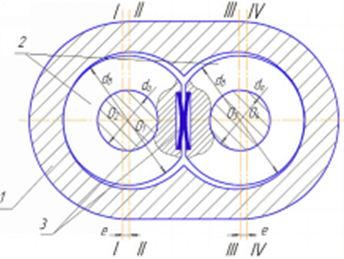
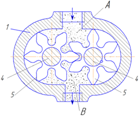
Fig. 1. Arrangement of two support bushings in the housing bores of the gear pump and the operating process: a) arrangement of two support bushings in the housing bores of the gear pump; b) operating process
The gear pump includes (see Fig. 1): housing – 1; support bushings – 2; elastic expanding elements – 3; shafts – 4; outer diameter of the support bushing – db; diameter of the bore of the support bushing – d0; I-I and III-III – axes of the pump housing bores; II and IV – axes of the support bushing bores; e – eccentricity; O1 and O3 – centers of the axes of the pump housing bores; O2 and O4 – centers of the axes of the support bushing bores; gears – 5; suction cavity – A; discharge cavity – B.
The gear pump operates as follows (see Fig. 1). The gear pump delivers oil (shown by arrows) from cavity A to cavity B by means of two gears 5 rotating on two support bushings 2 installed with a clearance fit in the pump housing 1. The bores in the support bushings 2 assembled in the pump housing 1 are manufactured with an eccentricity e in the direction of the center distance between the bores of the support bushings 2. When the support bushings 2 are expanded by the elastic expanding elements 3, a guaranteed clearance is provided between the outer diameter of the gear teeth of the gears 5 mounted on the support bushings 2 and the bore in the pump housing 1. As a result, the clearance between the housing 1 and the bushing 2 is reduced, which contributes to an increase in the output performance of the pump, since the pump capacity mainly depends on leakage of the working fluid through the clearances formed between the tips of the gear teeth and the pump housing.
Figure 2 shows the support bushings of the gear pump with a biaxial connection of the second design version.
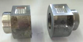
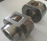
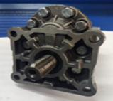
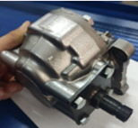
Fig. 2. Support bushings of the gear pump with a biaxial connection of the second version: a) support bushings with a machined groove; b) elastic expanding elements; c) assembled support bushings d), e) assembled gear pump with a biaxial connection
2 Materials and methods
2.1 Testing of an experimental gear pump with a biaxial connection
The testing was carried out under the conditions of the educational and research laboratory base of the Department of Technological Machines and Equipment of Kazakh Agrotechnical Research University named after Saken Seifullin. For laboratory testing, the experimental gear pump with a biaxial connection was installed and fixed on a special device for testing a gear pump with a biaxial connection, which was mounted on the carriage (instead of the tool holder) of a lathe. Figure 3 shows the mounted device for testing gear pumps based on a lathe.
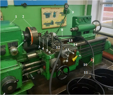
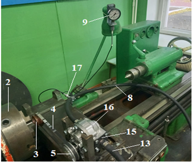
Fig. 3. Mounted device for testing gear pumps based on a lathe: а) front view; b) top view; 1 – lathe; 2 – three-jaw chuck; 3 – driving pulley; 4 – V-belt; 5 – driven pulley; 6 – plate; 7 – carriage; 8 – hose; 9 – pressure gauge; 10 – valve (shut-off cock); 11 – tanks; 12 – bracket; 13 – hose; 14 – bolts; 15 – flange; 16 – gear pump with a biaxial connection
The testing of the experimental gear pump with a biaxial connection was carried out in the following stages:
- Idle run test. The correctness of installation, the reliability of fastening of the gear pump with a biaxial connection, as well as the reliability of the connections of hoses, the pressure gauge, and the valve (shut-off cock) were checked.
- Verification of correct operation of the lathe (rotation of the three-jaw chuck, proper switching to different rotational speeds) and of the hydraulic system of the device (correct operation of the valve, pressure gauge, and absence of oil leakage).
- Load testing. Load testing was carried out in the following order. The lathe was started by setting the rotational speed to 200 rpm, and the start and end times of oil discharge into the oil collection container were recorded at three different positions of the valve (fully open, half-closed, and slightly open). The pressure gauge readings were recorded. The sequence of the experiment was repeated by setting the rotational speed in the range n=500÷3000 rpm. Variation of the rotational speed of the gear pump was carried out by rotating the three-jaw chuck, while the driven pulley with different diameters was installed. Using this methodology, the pump capacity, operating pressure in the system, and oil heating temperature were determined. For the purpose of comparing technological performance indicators, two gear pumps (a gear pump with a biaxial connection and a standard Gear pump-50U3) were tested under the same operating modes. Measurement of the oil heating temperature was carried out using a technical glass thermometer of the TTM direct type.
The working fluid used in the experimental tests was a mineral hydraulic oil corresponding to the ISO VG 46 viscosity grade. For this class of hydraulic oil, the typical kinematic viscosity is approximately 46 mm²/s at 40 °C. Before each test run, the initial oil temperature was maintained within 20-21 °C.
The operating pressure was measured using a technical pressure gauge with a measurement range of 0-25 MPa and an accuracy class of 1.5. Oil temperature measurements were performed using a direct-reading TTM-type technical glass thermometer with a measurement range from 0 to 100 °C and an accuracy of ±1 °C.
The obtained results are presented in Tables 1,2,3,4.
Table 1. Results of the study of the biaxial gear pump
|
Spindle speed, rpm |
Start time of oil discharge, sec |
End time of oil discharge, sec |
Total oil pumping time, sec |
Pumped fluid volume, liter |
Oil temperature, °C |
|
500 |
7 |
344 |
337 |
32 |
21 |
|
1000 |
8 |
176,5 |
168,5 |
32 |
21 |
|
1500 |
9 |
93 |
84 |
32 |
22 |
|
2000 |
2 |
65,2 |
67,2 |
32 |
24 |
|
2500 |
3 |
45 |
42 |
32 |
25 |
|
3000 |
6 |
39,5 |
33,5 |
32 |
27 |
Table 2. Results of the study of the standard Gear pump-50U3
|
Spindle speed, rpm |
Start time of oil discharge, sec |
End time of oil discharge, sec |
Total oil pumping time, sec |
Pumped fluid volume, liter |
Oil temperature, °C |
|
500 |
9 |
355,5 |
346,5 |
50 |
21 |
|
1000 |
10 |
183 |
173 |
50 |
21 |
|
1500 |
11 |
108 |
107 |
50 |
23 |
|
2000 |
5 |
78,4 |
73,4 |
50 |
24 |
|
2500 |
6 |
56 |
48 |
50 |
24 |
|
3000 |
7 |
45,5 |
39,5 |
50 |
25 |
The difference in pumped fluid volume during the experimental tests was associated with different testing objectives. For the standard gear pump, a pumped volume of 32 liter was sufficient to evaluate the main operating characteristics. In contrast, the biaxial gear pump equipped with elastic expanding elements was tested using a pumped volume of 50 liter to additionally assess thermal stability, oil temperature growth, and the operational behavior of support bushings under prolonged operating conditions.
Table 3. Results of the study of the biaxial gear pump
|
Valve position |
Rotational speed n, rpm |
|||||
|
500 |
1000 |
1500 |
2000 |
2500 |
3000 |
|
|
Pressure P, MPa |
||||||
|
Fully open |
3 |
5 |
6 |
7 |
9 |
10 |
|
Half-closed |
4,2 |
6,1 |
8,5 |
10,3 |
13,5 |
15 |
|
Slightly open |
5,2 |
8,7 |
12 |
16,8 |
20,8 |
24 |
Table 4. Results of the study of the standard Gear pump-50U3
|
Valve position |
Rotational speed n, rpm |
|||||
|
500 |
1000 |
1500 |
2000 |
2500 |
3000 |
|
|
Pressure P, MPa |
||||||
|
Fully open |
0,75 |
1,6 |
3,8 |
4,5 |
7,4 |
8,2 |
|
Half-closed |
0,86 |
2,1 |
5,3 |
6,4 |
9 |
12,7 |
|
Slightly open |
1 |
2,4 |
6,2 |
7,9 |
13,6 |
16,8 |
Figure 4 shows the graph of the influence of the rotational speed on the oil heating temperature in the system.
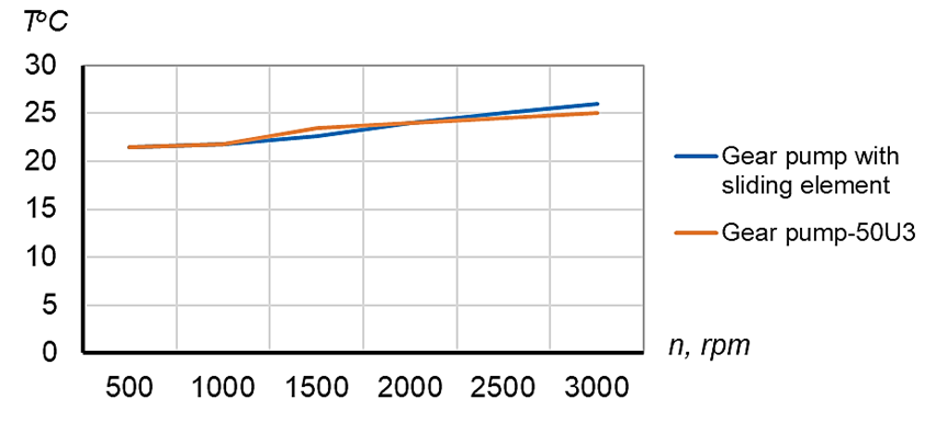
Fig. 4. Graph of the influence of rotational speed on the oil heating temperature in the system
Figure 5 shows the graph of the influence of the rotational speed on the pressure in the system.
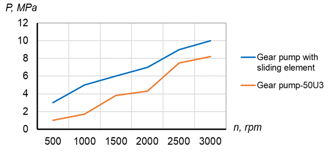
Fig. 5. Graph of the influence of rotational speed on the pressure in the system
Figure 6 shows the graph of the influence of the rotational speed on the pressure in the system at the half-closed position of the valve (shut-off cock).
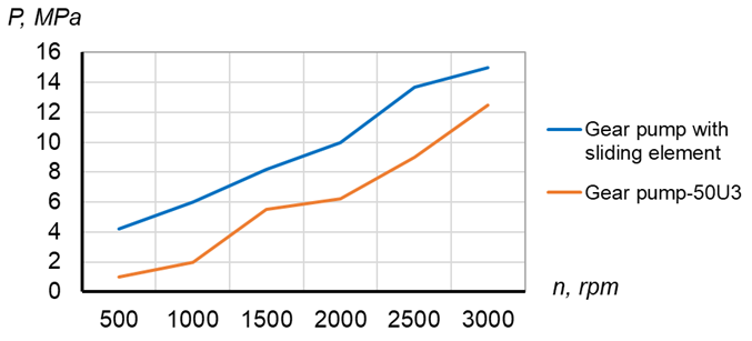
Fig. 6. Graph of the influence of rotational speed on the pressure in the system at the half-closed position of the valve (shut-off cock)
Figure 7 shows the graph of the influence of the rotational speed on the pressure in the system at the slightly open position of the valve (shut-off cock).
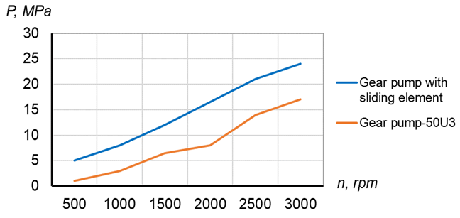
Fig. 7. Graph of the influence of rotational speed on the pressure in the system at the slightly open position of the valve (shut-off cock)
2.2 Simulation of the state of support bushings with expanding elements under load
To study and simulate the state of support bushings with expanding elements under load, NX Advanced Simulation, specifically the specialized computational module NX Thermal / NX Advanced Thermal, was used.
Figure 8 shows a model of the gear pump with a biaxial connection with installed expanding elements.
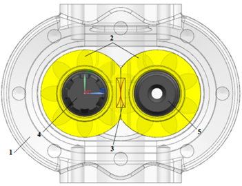
Fig. 8. Model of the gear pump with a biaxial connection with installed expanding elements: 1 – housing; 2 – bushing; 3 – elastic expanding elements; 4 – driving shaft-gear; 5 – driven shaft–gear
Figure 9 shows the calculated part, namely the support bushing with a plate (expanding element).
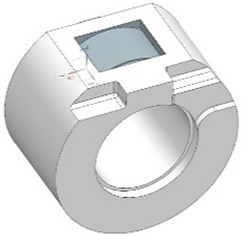
Fig. 9. Calculated part: support bushing with a plate (expanding element)
After opening the support bushing file in the Siemens NX CAD system, work on triangulation of the part was performed using the finite element method (FEM). A 3D tetrahedral FEM mesh was selected for triangulation of the part. For the finite element simulation, the support bushing was modeled as a structural steel component with a Young’s modulus of 2.1×10¹¹ Pa and a Poisson’s ratio of 0.30. The elastic expanding element was modeled as a spring steel component with a Young’s modulus of 2.0×10¹¹ Pa and a Poisson’s ratio of 0.29. These material properties were assigned in the Siemens NX Advanced Simulation environment to evaluate the stress-strain state of the bushing and the expanding element under load.
Figure 10 shows the FEM mesh of the bushing part with a plate.
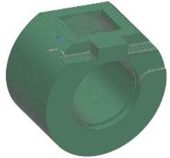
Fig. 10. FEM mesh of the support bushing with a plate
After triangulation, dynamic loads in the form of periodic pressure were applied to the plate. Boundary conditions were also specified on the inner surface of the bushing, since the bushing and the inner liner are mounted on the shaft–gear. The interaction between the elastic expanding element and the support bushing was defined as frictional sliding contact. This contact type was selected because, under load, the expanding element transmits pressure to the bushing surface while allowing limited relative displacement along the contact zone. Such an approach makes it possible to more realistically reproduce the mechanical interaction between the plate and the bushing compared with a fully bonded contact model. The pressure load applied to the plate was imposed in two stages: 10 and 15 bar at rotational speeds of 1000 and 1500 rpm, respectively.
Figure 11 shows the application of loads and boundary conditions to the investigated bushing part with a plate.
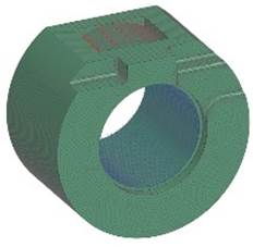
Fig. 11. Application of loads and boundary conditions to the bushing part with a plate
The study was carried out in two stages. At each stage, different input data were specified. Figure 12 shows the segments of the measurement results of the loads acting on the plate and the effect on the bushing housing, on the basis of which graphs of the pressure effect results were constructed.
|
|
|
|
a) |
b) |
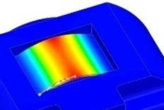
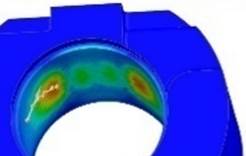
Fig. 12. Segments of the measurement results of the loads acting on the plate and the effect on the bushing housing, on the basis of which graphs of the pressure effect results were constructed: a) load measurement segment – from the lower part of the plate to its middle along an arc with a radius of 17 mm over a length of 10 mm; b) load measurement segment – along an arc from the minimum reaction to the maximum reaction on the inner surface of the bushing over a length of 10 mm
Figure 13 shows the state of the model after rotation of the shaft–gear of the gear pump with a biaxial connection at the specified input data. Input data:
- rotational speed – 1000 rpm;
- pressure load – 10 bar.

Fig. 13. Model showing the state of the product under a pressure load of 10 bar at 1000 rpm
Figure 14 shows the graph of the load measurement segment from the lower part of the plate to its middle along an arc with a radius of 17 mm over a length of 10 mm.
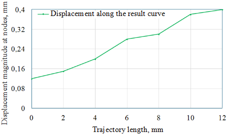
Fig. 14. Load measurement segment from the lower part of the plate to its middle along an arc with a radius of 17 mm over a length of 10 mm
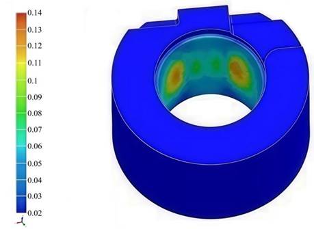
Fig. 15. Also shows a model displaying the reaction force of the plate acting on the bushing under a pressure load of 10 bar at 1000 rpm
Figure 16 shows the graph of the load measurement segment along an arc from the minimum reaction to the maximum reaction on the inner surface of the bushing over a length of 10 mm.
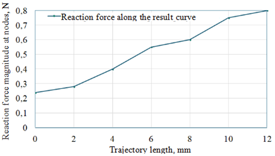
Fig. 16. Load measurement segment along an arc from the minimum reaction to the maximum reaction on the inner surface of the bushing over a length of 10 mm
Figure 17 shows the state of the model after rotation of the shaft–gear of the gear pump with a biaxial connection at the specified input data. Input data:
- rotational speed – 1500 rpm;
- pressure load – 15 bar.
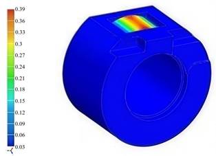
Fig. 17. Model showing the state of the product under a pressure load of 15 bar at 1500 rpm
Figure 18 shows the graph of the load measurement segment from the lower part of the plate to its middle along an arc with a radius of 17 mm over a length of 10 mm.
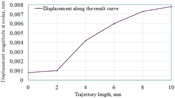
Fig. 18. Load measurement segment from the lower part of the plate to its middle along an arc with a radius of 17 mm over a length of 10 mm
Figure 19 shows the state of the model displaying the reaction force of the plate acting on the bushing under a pressure load of 15 bar at 1500 rpm.
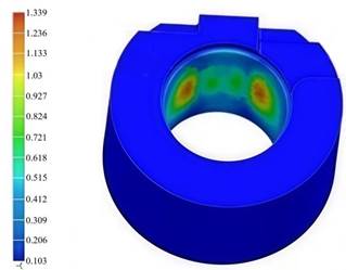
Fig. 19. Model showing the reaction force of the plate acting on the bushing under a pressure load of 15 bar at 1500 rpm
Figure 20 shows the graph of the load measurement segment along an arc from the minimum reaction to the maximum reaction on the inner surface of the bushing over a length of 10 mm.
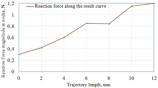
Fig. 20. Load measurement segment along an arc from the minimum reaction to the maximum reaction on the inner surface of the bushing over a length of 10 mm
The reaction force values shown in Figures 16 and 20 correspond to local nodal reaction forces obtained along selected measurement segments of the finite element mesh. Therefore, these values should not be interpreted as the total resultant force acting on the entire support bushing. The curves characterize local contact response zones between the expanding element and the bushing surface. For a complete assessment of the bushing loading state, local reaction force distribution should be considered together with stress distribution and deformation patterns.
3 Results and discussion
Tests of the gear pump with a biaxial connection equipped with support bushings with expanding elements showed positive results.
To improve the comparative analysis of pump performance, the volumetric efficiency of both the standard gear pump and the biaxial gear pump was additionally evaluated. The volumetric efficiency was determined as the ratio between the experimentally measured flow rate and the theoretical pump flow rate. The actual flow rate was experimentally determined from the ratio between the pumped fluid volume and the pumping time. The obtained results showed that the biaxial gear pump equipped with elastic expanding elements demonstrated higher volumetric efficiency compared to the standard pump under identical operating conditions. The improvement in volumetric efficiency is associated with reduced internal leakage due to more stable support bushing positioning and partial compensation of operational clearances. Based on the experimental data, the actual flow rate of the biaxial gear pump increased more intensively with rotational speed than that of the standard pump. This indicates improved volumetric performance of the proposed design. The increase is mainly explained by reduced internal leakage and more stable positioning of the support bushings due to the elastic expanding elements. According to the calculated values, the volumetric efficiency of the biaxial gear pump increased by approximately 8-12% compared with the standard Gear Pump-50U3.
The maximum pressure in the system of 25 MPa was achieved at a rotational speed of n = 3000 rpm with the valve (shut-off cock) in the slightly open position (see Fig. 7). With the valve fully open, the maximum pressure in the system was 10 MPa at a rotational speed of n = 3000 rpm (see Fig. 5).
With the valve in the half-closed position, the maximum pressure in the system was 15 MPa at a rotational speed of n = 3000 rpm (see Fig. 6). Depending on the rotational speed n, the oil heating temperature in the system was in the range of 22–27 °C (see Fig. 4). The maximum oil temperature Т = 27 0С was also observed at a rotational speed of n = 3000 rpm, while the minimum temperature value was observed at a rotational speed of n = 500 rpm (see Fig. 4).
It was established that an increase in the rotational speed has a positive effect on pump capacity, operating pressure in the system, and oil heating temperature. It was also found that, on average, the operating pressure generated by the gear pump with a biaxial connection is 1.2 times higher than that of the standard Gear pump-50U3 pump (see Tables 1 and 2). The increase in operating pressure should be interpreted as a comparison of pressure values obtained under identical rotational speeds and the same valve positions for both pumps. Therefore, the obtained results characterize higher achievable pressure under comparable laboratory operating conditions rather than a complete shift of the overall pump characteristic curve.
During the testing process, no oil leakage or air accumulation in the high-pressure hose was detected, and the pressure gauge operated properly.
An increase in pressure to 15 bar (at 1500 rpm) acting on the plate interacting with the bushing leads to a significant increase in the reaction force and loads on the joint (see Figs. 16 and 18). The increase in force can be explained by the fact that it is directly proportional to the applied pressure and the contact area. However, an excessive increase in the reaction force and load is undesirable, since this leads to an increase in sliding friction between the plate and the bushing, which accelerates wear of the contact surfaces. It is also known [13,14,15] that high pressure and rotational speed can cause vibrations, material fatigue, and deformation.
The increase in the reaction force of the plate acting on the bushing ΔR with an increase in pressure to 15 bar is directly proportional to the effective contact area and is determined by the expression:
where Sеff is the projected area of the contact surface.
The pressure force acting on the plate and transmitted to the bushing depends on the effective area Sеff (the projection of the contact area onto a plane perpendicular to the pressure vector). The increase in the reaction force due to pressure is calculated using the formula above:
At a pressure of 15 bar, this value amounts to 1.5 · 106 N per square meter of area.
The loading conditions of the bushing in a specific zone, where the load on the inner surface increases along an arc with a radius of 17 mm and a length of 10 mm (see Figs. 17 and 19), indicate a non-uniform stress distribution. The contact zone has a curvilinear nature, and it is important to take into account stress concentration and wear.
The FEM results are consistent with the experimental findings. The simulation showed that the elastic expanding element retained its geometric profile and mechanical properties under load, while providing local contact interaction with the support bushing. This behavior explains the experimentally observed increase in operating pressure of the biaxial gear pump compared with the standard Gear Pump-50U3. The expanding element contributes to clearance compensation between the bushing and the pump housing, which reduces internal leakage paths and improves the functional stability of the pump. At the same time, the increase in local contact pressure explains the slight rise in oil temperature observed during the tests. Therefore, the combined experimental and FEM results confirm the functional performance validation and design robustness of the proposed biaxial gear pump with elastic expanding elements.
4 Conclusions
The results of testing the gear pump with a biaxial connection showed that:
- the obtained values of operating pressure generated by the proposed gear pump design with a biaxial connection at various valve positions demonstrate that, on average, they are 1.2 times higher than the operating pressure of a standard gear pump. This is achieved due to a larger contact area and more uniform load distribution between the gear teeth in the gear pump with a biaxial connection.
- the slight increase in oil temperature by approximately 1.8-2 °C in the biaxial gear pump may be associated with increased local mechanical interaction between the elastic expanding element and the support bushing surface. Since the expanding element reduces the clearance between the bushing and the housing, local contact pressure and sliding friction may slightly increase. However, the observed temperature rise remained within a small range and did not lead to critical overheating. Therefore, the proposed clearance compensation mechanism can be considered thermally stable under the tested operating conditions.
As a result of modeling the state of support bushings with expanding elements under load, it was established that the elastic expanding element maintains its profile and mechanical properties under deformation.
Overall, the results of experimental testing and computer simulation confirmed the operability of the design of the gear pump with a biaxial connection and expanding elements.
Acknowledgements
No external funding was received for this research.
References
- Lepeshkin, A. V., Mikhaylin, A. A., & Sheypak, A. A. (2003). Hydraulics and hydraulic-pneumatic drive: Part 2. Hydraulic machines and hydraulic-pneumatic drives (A. A. Sheypak, Ed.). Moscow State Industrial University.
- Bashta, T. M., Rudnev, S. S., Nekrasov, B. B., Baybakov, O. V., & Kirillovskiy, Y. L. (1982). Hydraulics, hydraulic machines and hydraulic drives (2nd ed.). Mechanical Engineering.
- Syritsyn, T. A. (1990). Operation and reliability of hydraulic and pneumatic drives. Mechanical Engineering.
- Lezin, P. P. (1997). Fundamentals of reliability of agricultural machinery. Mordovia University Publishing House.
- Zhabo, V. V., & Uvarov, V. V. (1984). Hydraulics and pumps (2nd ed.). Energoatomizdat.
- Rybkin, E. A. (1960). Gear pumps for metal-cutting machine tools. Mashgiz.
- Yudin, E. M. (1964). Gear pumps. Mechanical Engineering.
- Osipov, A. F. (1971). Positive displacement rotary hydraulic machines. Mechanical Engineering.
- Sherov, A. K., Alikulov, D. E., Smirnov, Y. M., Sherov, K. T., Rakishev, A. K., Mussayev, M. M., & Mazdubay, A. V. (2021). Research of the internal leakage process of a liquid in the design of a gear pump with a two-axial connection. News of the National Academy of Sciences of the Republic of Kazakhstan. Series of Geology and Technical Sciences, 2(446), 198–204. https://doi.org/10.32014/2021.2518-170X.53
- Sherov, A. K., Sherov, K. T., Sikhimbayev, M. R., Absadykov, B. N., & Kuanov, I. S. (2021). Research of qualitative indicators of a gear pump with two-shaft connection for pumping petroleum products. News of the National Academy of Sciences of the Republic of Kazakhstan. Series of Geology and Technical Sciences, 4(448), 108–116. https://doi.org/10.32014/2021.2518-170X.88
- Sherov, A. K., Myrzakhmet, B., Sherov, K. T., Sikhimbayev, M. R., & Absadykov, B. N. (2021). Gear pump quality improving by changing the design and size of the support bushings. News of the National Academy of Sciences of the Republic of Kazakhstan. Series of Geology and Technical Sciences, 6(450), 155–162. https://doi.org/10.32014/2021.2518-170X.132
- Sherov, A. K., Myrzakhmet, B., Sherov, K. T., Absadykov, B. N., & Sikhimbayev, M. R. (2022). Method for selecting the location of the clearance fields of the landing surfaces of gear pump parts with a biaxial connection. News of the National Academy of Sciences of the Republic of Kazakhstan. Series of Geology and Technical Sciences, 1(451), 159–166. https://doi.org/10.32014/2022.2518-170X.153
- Morales-Espejel, G. E., & Gabelli, A. (2018). Rolling bearing seizure and sliding effects on fatigue life. Proceedings of the Institution of Mechanical Engineers, Part J: Journal of Engineering Tribology, 233(3), 353–363. https://doi.org/10.1177/1350650118779174
- Hooke, C. J., & Morales-Espejel, G. E. (2018). Rapid analysis of low-amplitude sinusoidal roughness in rolling-sliding elastohydrodynamic contacts including thermal effects. Proceedings of the Institution of Mechanical Engineers, Part C: Journal of Mechanical Engineering Science, 232(9), 1690–1706. https://doi.org/10.1177/0954406217709590
- Kovshov, A. G. (2020). Influence of dynamic loading parameters under vibro-friction on equivalent stresses and wear rate in sliding contact. Proceedings of the Samara Scientific Center of the Russian Academy of Sciences, 22(3), 98–102. https://doi.org/10.37313/1990-5378-2020-22-3-98-102
- Yang, H. W., Jang, H. S., & Ji, S. (2026). Volumetric efficiency prediction of external gear pumps using a leakage model based on dynamic clearances. Actuators, 15(1), 56. https://doi.org/10.3390/act15010056
- Cieślicki, R., & Karpenko, M. (2022). An investigation of the impact of pump deformations on circumferential gap height as a factor influencing volumetric efficiency of external gear pumps. Transport, 37(6), 373–382. https://doi.org/10.3846/transport.2022.18331
- Szwemin, P., Fiebig, W., & Filo, G. (2021). The influence of radial and axial gaps on volumetric efficiency of external gear pumps. Energies, 14(15), 4468. https://doi.org/10.3390/en14154468
- Peng, Z., Wei, L., Liu, R., Liang, M., & Qiang, Y. (2023). Flow field modeling and simulation of high-speed gear pump considering optimal radial and end clearance. IEEE Access, 11, 64725–64737. https://doi.org/10.1109/ACCESS.2023.3290079
- Novaković, B., Radovanović, L., Zuber, N., Radosav, D., Đorđević, L., & Kavalić, M. (2022). Analysis of the influence of hydraulic fluid quality on external gear pump performance. Eksploatacja i Niezawodnosc – Maintenance and Reliability, 24(2), 260–268. https://doi.org/10.17531/ein.2022.2.7
Conflict of Interest Statement
The authors declare that they have no conflict of interest.
Author Contributions
Data Availability Statement
There is no dataset associated with this study or the data are not publicly available.
Supplementary Materials
There are no supplementary materials associated with this article.