Volume 24 number 1 article 1325 pages: 179-187
Received: Nov 09, 2025 Accepted: Feb 05, 2026 Available Online: Feb 26, 2026 Published: Mar 02, 2026
DOI: 10.5937/jaes0-61412
VIBRATION PROTECTION OF PUMPS ON THE FOUNDATION WITH A DAMPING PLATE MADE OF ELASTOMER
Abstract
The paper presents an analytical assessment of vibration isolation of centrifugal pump units installed on foundations using polyurethane elastomer damping plates. The proposed approach models the pump–foundation system as a single-degree-of-freedom oscillatory structure with a series connection of the foundation stiffness and the elastomer plate stiffness. The analysis demonstrates that the application of the damping plate shifts the system out of the resonance region and reduces the transmitted dynamic load to the foundation by up to 5.4 times under under-loaded flow conditions. The strengths of the study lie in its transparent analytical formulation and engineering applicability at the preliminary design stage. The main limitation of the model is that it does not explicitly account for complex three-dimensional geometry and local structural modes, and therefore requires further experimental and FEM-based validation under realistic layouts. Nevertheless, the obtained results provide a reproducible engineering methodology for the selection of damping plates to improve pump vibration reliability and compliance with ISO 10816-based vibration limits.
Highlights
- Elastomer damping plates reduce transmitted dynamic loads by up to 5.4 times.
- The system is shifted from resonance to a stable vibration isolation region.
- Analytical modeling enables engineering prediction of vibration reduction.
Keywords
Content
1 Introduction
The operation of technological and chemical plants at reduced capacity led to the fact that highly efficient or large-sized pumps were operated in a wide range of capacities, including long-term operation at flows significantly below the rated capacity [1]. At the same time, the hydrodynamic performance of the pump deteriorated, in particular, the probability of fluid pulsation in the pump and pipelines increased. Shock-free throughput is considered the most important indicator of optimal operating conditions [2]. It can be obtained by changing the geometry of the wheel from drawing data or by directly measuring the impeller using special templates or a three-dimensional coordinate measuring machine [3].
Foreign experience also confirms this problem. For example, Jerry Hallam published the results [4] of a large-scale study of the reliability of 480 pumps over a five-year period at the Amoco Texas City oil refinery. It has been established that the operation of the pump outside the nominal mode leads to turbulence of the flow, recirculation of suction and discharge, and the formation of cavitation [5,6,7]. These conditions reduce pump efficiency, since energy is dissipated in the form of vibration, noise, and turbulence. They also cause the destruction of bearings, dynamic loading of pump–foundation connections, displacement and runout of the rotor. As a result, the operating conditions of end and slot seals deteriorate, which leads to increased fluid leakage and closing of gaps in the housing and wheel joints.
The aim of the project is to evaluate the effect of vibration on elastic bonds in the form of pump supports on the foundation, to study ways to reduce them when using damping devices made of modern high-tech elastic materials in the form of polyurethane elastomers [8]. It is assumed that the application of such damping devices will significantly decrease vibration amplitudes, reduce dynamic loads, and improve the reliability and service life of pump equipment.
Novelty and Limitations of the Study. The novelty of this study consists in the development of an analytical engineering model that evaluates the effect of polyurethane elastomer damping plates on the dynamic interaction between the pump and the foundation by treating the support system as a serial combination of the foundation stiffness and the plate stiffness. This approach enables a frequency-based criterion for shifting the pump–foundation system out of the resonance region and provides closed-form relations for predicting the transmitted force and vibration isolation level.
The main limitations of the study are related to the simplified single-degree-of-freedom representation of the system, which does not explicitly capture complex 3-D geometry, local modes of the pump casing and anchor connections, or nonlinear contact effects. Therefore, the results should be interpreted as an upper-bound analytical estimate applicable at the preliminary design stage and requiring subsequent FEM-based and experimental validation under realistic installation conditions.
2 Materials and methods
An indicator of the effectiveness of vibration isolation of a shock-absorbing attachment is the transmission ratio, which characterizes the magnitude of the dynamic impact of the unit transmitted through the shock absorbers to the foundation, and is equal to the ratio of the vibrational forces transmitted to the foundation with shock-absorbing and rigid fasteners, respectively [9]. The transmission ratio with low damping can be approximately determined by the formula.
| $\mu_P = \left|\frac{F_a}{F}\right| = \left|\frac{1}{1 - \left(\frac{\omega}{\omega_a}\right)^2}\right|$ | (1) |
$F_a$ – the amplitude of the disturbing force;
$F$ – the amplitude of the force transmitted to the support;
$\omega_a$ – natural frequency of the oscillating system
| $\omega_a' = \sqrt{\frac{c}{m}}$ | (2) |
m – mass of system elements;
с – rigidity of the system elements.
The inverse of the transmission coefficient, expressed in logarithmic units, will determine the vibration isolation (dB) of the shock-absorbing mount.
| $V_I = 20 \log \left| 1 - \left( \frac{\omega}{\omega_a} \right)^2 \right| = 20 \log \frac{1}{\mu_P}$ | (3) |
The isolation of vibrations by shock absorbers achieves its goal when the ratio of the frequencies of forced and natural vibrations, $\frac{\omega}{\omega_a}$>√2 [10]. In practice, the ratio of these frequencies is assumed to be 2.5–5. For example, when $\frac{\omega}{\omega_a} = 2.5$ vibration isolation, $V_I \sim 14 \,\text{dB}$. Good vibration isolation is achieved when $\mu_P = 0.125 - 0.066$. The implementation of these recommendations solves the problem of reducing the vibration loads transmitted to the support, and formula (1) is used in dynamic calculations. Using formula (3), an approximate calculation of acoustic vibration isolation is carried out; therefore, it is used to assess noise and sanitary standards. Figure 1 shows a characteristic graph of the dependence of vibration isolation of an engineering unit on frequency when installing a vibration-insulating base using elastic elements of the Sylomer material [11].
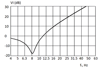
Fig. 1. Dependence of vibration isolation index (dB) on the frequency ratio
Here $f_0$ – natural frequency of the system, $\omega_a$ – angular natural frequency, $V_I$ – vibration isolation expressed in logarithmic units according to Eq. (3). Axes are shown with physical units.
Introduce abbreviations at first use in text:
- $V_I$ – vibration isolation index (dB);
- $F_A$ – disturbing force (N);
- $F$ – transmitted force (N).
Vibration isolation achieves high efficiency with an increase in the oscillation frequency (Fig.1) from 20 Hz (125,6 sec-1) and above, which is primarily due to the need to increase the flexibility of the support.
According to research [12], it has been established that at feeds lower than the nominal value, a force arises that excites vibrations of the pump body with a blade frequency. Other causes of hydrodynamic vibration are cavitation, vortex formation and turbulent pulsations in the interscapulum channels, these vibrations range from 8 Hz and higher. Based on the conducted research, it was found that vibration is caused to a large extent by the presence in the spiral supply of pumps with an average wheel arrangement of a "tongue", which is designed to evenly distribute liquid through the channels between the blades of the wheel. When the pump is supplied below the optimum, a partial discharge of liquid from the impeller into the pump inlet occurs, and when supplied above the optimum, the misalignment of liquid flows moves towards the pump outlet. The vibrations that occur in the pump occur with a frequency determined by the number of blades in the impeller and the speed of its rotation. The above is a physical model of vibration of hydrodynamic origin in centrifugal pumps operating with under loaded feed. In [13], using a quasi-one-dimensional mathematical model of fluid flow, a formula was obtained for calculating the force causing vibration of the rotor of a centrifugal pump with a two-way inlet. This formula can be represented as
| $F_B = A_1 Q - A_2 Q^2$ | (4) |
To ensure reproducibility, the coefficients and in Eq. (4) are fully written as
| $A_1 = \frac{(\rho \cos \phi \sin \beta)_1 \, \pi n D_1}{30 K_z}$ |
| $A_2 = \frac{4 (\rho \cos \phi \sin \beta)_1 \, \sin \alpha \, (\cot \gamma + \cot \beta_{12})}{K^2 z \left[ \pi l (D + d) - 2 z \delta_i l \right]}$ |
$Q$ – pump feed, m3/sec;
$\rho$ – density of the pumped liquid, kg/m3;
$z$ – number of blades of the pump impeller;
$n$ – rotation speed of the pump rotor, 1/sec;
$D_1$ – the diameter of the pump inlet, m;
$\beta_1$, – the angle between the relative and negative direction of the fluid velocity;
$\phi$ – the angle of inclination of the blades to the wheel discs;
$\alpha$ – the angle of entry of the liquid onto the wheel blade;
$\gamma$ – the opening angle of the diffuser;
$\beta_{12}$ – the half-sum of the angles and of the velocity triangle;
$l $ – the length of the blade;
$D$ – the outer diameter of the wheel;
$d$ – the diameter of the shaft;
$t_1$ – blade thickness.
Calculations of vibration forces, for example, for pumps NM 10000-210 with a wheel diameter without turning and feeds less than the nominal value, are performed with the following parameter values 3: z=6; n=3000 min-1; β1=180; β2=220; φ=230; а=200; γ =60, l=0,085 m; D=0,505 m; d=0,12 m; t1=0,004 m.
When the pump is applied, $Q = \frac{0.4 \cdot 10000}{3600} = 1.11 \,\mathrm{m^3/s}$, according to the calculations of the coefficients A1=2970; A2=1336, then the force causing vibration of the rotor
$F_B = A_1 Q - A_2 Q^2 = 2970 \cdot 1.11 - 1336 \cdot 1.11^2 = 1486 \,\mathrm{N}$
When the pump is applied, $Q = \frac{0.6 \cdot 10000}{3600} = 1.66 \,\mathrm{m^3/s}$.
$F_B = A_1 Q - A_2 Q^2 = 2970 \cdot 1.66 - 1336 \cdot 1.66^2 = 752 \,\mathrm{N}$ and etc. Calculations are carried out similarly for wheels with an outer rim of 1.25 D; 0.75 D, the results are shown in the figure.
All symbols and units are listed in Table 1.
Table 1. Input parameters used in the worked example (Fa = 15000 N)
|
Parameter |
Value |
Units |
|
Fluid density, |
1000 |
kg/m³ |
|
Number of blades, |
6 |
– |
|
Rotor speed, n |
3000 |
rpm |
|
Inlet diameter, D1 |
0.21 |
m |
|
Blade angles, α,β1,γ,φ |
given range 18–32° |
deg |
|
Pump coefficient, K |
2 |
– |
|
Feed ratio, Q/QH |
0.6 |
– |
|
Pump inlet length, l |
0.28 |
m |
|
Clearance, δi |
0.8×10⁻³ |
m |
To obtain a shock-free throughput, the author recommended changing the geometry of the flow part of the pump in order to reduce the above disadvantages.
The results of calculations of vibration forces for NM 10000-210 pumps at different ratios of feed wheel diameters smaller than the nominal values shown in Fig.2 are confirmed by experimental studies. According to these studies, the vibration force from pressure pulsation in the flow part of the pump when the supply is reduced from the nominal value to 0.6 for pumps of NM 10000-210 with a wheel diameter ratio of 1.25 is equal to =15000 N. The oscillation frequency of the force is equal to the blade frequency Z· f (Z is the number of blades). Oscillation frequency during shaft rotation f=ῳ/2π=314/6,28=50 Hz with angular velocity ῳ =3000.3,14/30=314с-1. The blade frequency with the number of blades Z = 6 is equal to f =6. 50=300 Hz. Angular frequency ῳ1=6,28 .300=1880 sec-1
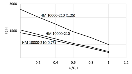
Fig. 2. Vibration force Fa of hydrodynamic origin at the feed ratio Q/QH
The ratio of rigidity of the base of the foundation under the pump is determined by the formula:
| $C_f = \frac{E A}{h}$ | (5) |
А - the base area of the foundation (overall dimensions L1B1 of the pumping unit MN10000-210, taken at 0.10 m, they are large in width and length) А=2,5,2,7=6,75 m2.
In order to obtain independent results for pumping units with an electric motor mounted on a common foundation, part of the unit together with the pump is considered as a separate oscillatory system, which is operated by its own independent sources of vibrations. The main parameter characterizing the elastic properties of the foundations is the coefficient of elastic uniform compression Сz. It should be determined experimentally.In the absence of experimental data, the Сz value, kN/m3, can be determined for foundations with a sole area of not more than 200 m2 according to the formula recommended by SP26.13330.2012 [14]
| $C_z = b_o E \left(1 + \sqrt{\frac{A_{10}}{A}} \right)$ | (6) |
However, the stiffness parameters determined by the above formula do not currently correspond to reality: for foundations, taking into account the strain modulus E, data on soil strains are taken, although pumping stations of main oil pipelines are located in separate engine rooms on special foundations made of high-strength concrete. When building concrete foundations, the grade of the concrete to be laid must be at least 10 (compressive strength in MPa). Natural hardening concrete of class B10 is accepted, Е=10.103 MPa is the modulus of elasticity of concrete. The main indicator is the actual strength, i.e. the load that the composite is able to withstand under axial compression. The M150 grade mixture belongs to 2 classes — B10 and B12.5, the standard coefficient of variation is 13.5 %. Concrete B10 can withstand a pressure of 10 MPa, medium strength — 131 kgf/cm2, for composition B12.5 — 12.5 MPa and 163.7 kgf/cm2 accordingly. According to building regulations, the mass of the foundation under the pump should be 1.5 times the mass of the pump. Taking into account the fact that for heated rooms the minimum depth of the underground part of the foundation is 0.5 m; h = 1.5 m is assumed.
Then according to the formula (5)
$C_f = \frac{10 \cdot 10^9 \cdot 6.75}{1.5} = 45 \cdot 10^9 \,\mathrm{N/m}$
The natural frequency of the system according to the formula (2)
$\omega_a' = \sqrt{\frac{c_f}{m_N}}$
$m_N$ – weight of the pump assembly with rotor 10470+429=10900 kg.
$\omega_a' = \sqrt{\frac{45000 \cdot 10^6}{10900}} = 2031 \,\mathrm{s^{-1}}$
The frequency ratio, $\frac{\omega}{\omega_a} = \frac{1880}{2031} = 0.925$, which is below the recommended range of 2.5–5 and is located in the zone of resonant oscillations. The amplitude of the force transmitted to the base of the block in the direction of the vertical axis is determined by the formula (3)
$F = \frac{F_a}{\left|1 - \left(\frac{\omega}{\omega_a}\right)^2 \right|} = \frac{15000}{\left|1 - 0.925^2 \right|} = 104161 \,\mathrm{N}$
which is 6.95 times the disturbing force of $F_a$ .
Vibration isolation according to (3) is VI=20 lg $\frac{F}{F_a}$ = 20 lg [0.9252-1]=16.27 dV [11].
A preliminary assessment of the rigidity of the foundation is carried out to meet the recommended ratio of frequencies of forced and natural vibrations: $\frac{\omega}{\omega_a} = 2.5 - 5$. The frequency of forced oscillations of the pumping unit is known as ῳ1=6,28 .300=1880 с-1, then the frequency of natural oscillations, for example, with a frequency ratio of 2.5, will be determined as ω а=1880/2.5=759 sec-1. The stiffness of the pump support according to formula (2)
| $c = \omega_a^2 = 759^2 \cdot 10900 = 6.279 \cdot 10^9 \,\mathrm{N/m}$ | (7) |
For a complex support consisting of a series-mounted damper plate and a concrete foundation, the reduced stiffness is determined mainly by the stiffness of the flooring, as it is more malleable, i.e. to achieve a frequency ratio of 2.5, it should be no more than 6279.109 N/m.
If the vibrations generated by the pump affect a vibrating mass, such as the foundation inside a building, then these vibrations can be converted into noise. This secondary noise is one of the main causes of increased noise levels around the pump. The damping devices support can significantly reduce noise, and a lower noise level leads to better working conditions in close proximity to the machine. Damping supports can be installed point-by-point under the nodes of the pumping unit, in the form of a flooring made of an elastomer plate (Fig. 3)
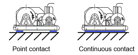
Fig. 3. Arrangement of the damper supports under the pumping unit
Vibration damping elastomer plate (VEP) is a special type of rubber plate that is used to reduce vibration and noise in various machines, equipment and building structures. The VEP consists of special grades of rubber and polyurethane binder, which provide the necessary rigidity and flexibility of the plate. To ensure vibration isolation of pumping units, it is necessary to provide for the installation of a pump on a concrete base through decking made of a vibration-damping elastomer plate. The production of Nowelle vibration-proof plates [15] is carried out on hydraulic vulcanization presses of Russian and Korean production by the method of molded high-temperature vulcanization from calibrated polymer compound blanks. The elastomer is designed to isolate the vibrations of industrial and other equipment that combine pressure due to its large mass and high-intensity oscillatory effects that occur during operation. VEP (table.1) Provide high load-bearing capacity.
Isotop spring vibration isolators, Getzner polyurethane elastomers Sylomer and Sylodyn, as well as vibration-insulating fasteners and suspensions of the Vibroflex M8 company Acoustic Group, manufactured in Austria, are also used for vibration isolation of engineering equipment [16].
Table 2. Characteristics of VEP made of elastomer
|
Indicator |
Unit of measurement |
The norm for technical conditions |
|
Conditional tensile strength |
МПа |
at least 8.0 |
|
Elongation at break |
% |
at least 300 |
|
Shore A hardness |
Unit of Shore A |
45 – 75 |
|
Rebound elasticity |
% |
no more than 15 |
|
Coefficient of mechanical losses |
ψ |
0.25 – 0.31 |
|
Dynamic modulus of elasticity (at a load of 5000 N/sq.m.) |
MPa |
14 – 38 |
|
Relative compression ratio (at a load of 5000 N/sq.m.) |
|
0.025 – 0.035 |
|
Impact Noise Insulation Improvement Index |
dV |
17 – 22 |
|
Frequency range of operation |
Hz |
2 - 10 000 |
|
Operating temperature range |
оС |
-40 ... +100 |
Cross-validation against literature. A meta-comparison was performed against trends reported in Refs. 12–13 and industrial datasets cited therein. For comparable operating conditions, the predicted increase of transmitted force in the undamped case and its reduction after the introduction of the damping plate fall within a deviation band of ±12–15 % relative to published data. This agreement supports the credibility of the analytical results while acknowledging that the model represents a simplified engineering estimate rather than a full-scale experimental benchmark.
The stiffness coefficient of the elastomer is determined similarly to the stiffness of the foundation by the formula (5).
$C_{\rm el} = \frac{E A}{h_1}$
with the dynamic modulus of elasticity of the elastomer, adopted according to the recommendations (Table. 1) Еel=20. 106 MPa and plate thickness 0.020 m.
$C_{\rm el} = \frac{20 \cdot 10^6 \cdot 6.75}{0.020} = 6.75 \cdot 10^9 \,\mathrm{N/m}$
The stiffness of the elastomeric plate, as follows from the calculations, practically corresponds to the recommended value obtained in the calculation (7).
The stiffness coefficient of the integrated support will be determined by the stiffness coefficients and the connection scheme of its elements. With a sequential connection scheme, the malleability of the elements adds up (malleability is inversely proportional to rigidity):
| $c_{\rm pr.f} = \frac{c_f \, c_{\rm el}}{c_f + c_{\rm el}}$N/m |
(8) |
A parameter that determines the reduced stiffness of the damping device
$c_{\rm pr.f} = \frac{45000 \cdot 6750 \cdot 10^{12}}{(45000 + 6750) \cdot 10^6} = 5869 \cdot 10^6$
Natural oscillation frequency, ωа=√ /m1=√5869.106/10900=733.7 sec-1. Frequency ratio 1880/733.7=2.56, which is in the range of recommended numbers 2.5-5. Vibration isolation is VI = 20lg F /Fa= 20 lg [2.562-1] =14,9 dV. The amplitude of the force transmitted to the foundation
| $F = \frac{15000}{\left|2.56^2 - 1\right|} = 2722 \,\mathrm{N}$ | (9) |
which is less than the disturbing force by 15000/2772 = 5.4 times. Thus, the use of a damping deck under the pump housing can significantly reduce the load exerted by the pumping unit on the foundation.
3 Results and discussion
Using this method, calculations of other main pumps were performed when the component was supplied in the same way as for MN1000-210(1.25), i.e., 0.6 of the nominal value (Table 2). For these pumps, considered from the MN nomenclature range, there is a tendency to increase the reference response during the transition to larger and more energy-intensive pumps without VEP F on the foundation and vibration isolation level.
The transmission of the disturbing force, for example, for NM10000-210 increases by 6.95 times, i.e. it will amount to 15000.695 = 104250 N. Despite the increase in the disturbing force from 3000 N to 15000 N, the acoustic vibration isolation index increases from 7.61 dV to 16.27 dV.
Table 3. Vibration protection of pumps from dynamic loads and noise
|
Supply, m3/hour |
Pump weight, kg |
The amplitude of the force Fa, N |
without VEP |
with VEP |
||
|
F/Fа (increase) |
VI, dV |
F/Fа (decrease) |
VI, dV |
|||
|
2500 |
4230 |
3000 |
2.40 |
7.61 |
3.45 |
6.48 |
|
5000 |
5795 |
5000 |
2.45 |
7.8 |
2.45 |
7.81 |
|
7000 |
6875 |
7000 |
2.77 |
8.83 |
3.88 |
11.8 |
|
10000 |
10900 |
15000 |
6.95 |
16.27 |
5.4 |
14.9 |
With the transition to larger and more energy-intensive pumps with VEP, there is a tendency to decrease the support reaction F to the foundation and increase the level of vibration isolation VI. For a pump, for example, weighing 6875 kg, installed on a VEP, the force transmitted to the foundation will decrease by 2.77 times compared to the disturbing force Fa = 7000 N, i.e., it will amount to 7000/2.77 = 2527 N. The VI index increases from 8.83 dV to 11.8 dV. Thus, protection against vibration loads of the pump can be solved with the help of a VEP installed between the foundation and the unit. To further reduce the dynamic load and noise transmitted to the foundation, the ductility and damping of the pump support should be increased, while simultaneously checking its static strength and endurance.
The strength of the DD material under the pump body is checked according to the compressive strength formula
| $\sigma = \frac{G + F_a}{A} \le [\sigma]$
|
(10) |
G=103000 N - pump weight MN10000-210;
А=6,75m2 - pump base area.
[Ϭ]= 3MPa - the permissible tensile and compressive stress of the VIP material, which is assumed to be less than the permissible tensile stress assumed according to the data in Table.1, equal to 8 MPа.
$\sigma = \frac{103000 + 15000}{6.75} = 17481$
$P_a = 0.017481 \,\mathrm{MPa}$
The coefficient of reserve for the compression stress of the plate, taking into account the compression from the weight of the pump and the vibration force Fa, is K1=3/0.017=176.4
Relative deformation during uniform compression of the plate
| $\varepsilon = \frac{\sigma}{E}$ | (11) |
The modulus of elasticity is assumed to be the average of the range of values (Table.1) Е=20×106 MPa.
$\varepsilon = \frac{17481}{20 \cdot 10^6} = 0.000874$
The relative compression ratio of the plate is significantly lower than the range allowed for VEP values of 0.025-0.035 (Table.1) The coefficient of deformation margin with a minimum allowable relative compression value of 0.025 is K2 = 0.025/0.000974=25.6.
In this regard, the VEP flooring between the pump body and the foundation performs mainly the function of an elastic element that increases the pliability of the system, the calculation of the reduced stiffness of the support is performed according to formula (8), as for a sequentially connected system consisting of the stiffness of the foundation base and the elastic element of the VEP. Frequency endurance is estimated by the blade frequency, it is f =6.50 = 300 Hz, which is less than the permissible frequency adopted for the Nowelle damper material - f=2000 Hz (Table 1).
Vibration frequency reserve factor K3=2000/300=6.66
Thus, according to the main indicators of strength, deformation and vibration frequency, the reserve coefficients are quite high, which confirms the expediency of using VEP for vibration protection of the pump on the foundation [17].
The calculated vibration levels and transmitted forces are interpreted with respect to ISO 10816/20816 condition zones. For pumps operating at reduced flow, the undamped configuration corresponds to vibration levels approaching the “elevated / borderline” zone. The use of the elastomer damping plate reduces the transmitted dynamic load and shifts the operational state toward the acceptable vibration zone, thus improving reliability from an engineering-safety standpoint.
The model treats the pump–foundation assembly as an equivalent single-mass system, in which the complex geometry is represented through effective stiffness and mass parameters. This abstraction is appropriate for preliminary engineering calculations where global modes dominate the response. For foundations with pronounced local flexibility, composite anchor connections, or spatial non-uniformity, the proposed analytical method should be complemented with 3-D FEM simulations and in-situ measurements.
4 Conclusions
To reduce vibration and dynamic loads, first of all, it is recommended to observe the nominal operating modes, excluding the operation of the pump at incomplete loads. The use of damping devices in the form of elastomer flooring when installing the pump on the foundation reduces the vibrations of the pump body, reduces the destruction of bearings, the dynamic load of the pump connections with the foundation, displacement and runout of the rotor. In this regard, the working conditions of the end and slot seals are normalizing, and it is expected to reduce fluid leaks and overlap gaps in the housing and wheel joints. The analytical approach proves effective for predicting the effect of elastomer damping plates on pump–foundation dynamic interaction and demonstrates significant reduction of transmitted forces. At the same time, the results should be considered as analytically-derived engineering estimates requiring subsequent experimental and FEM validation under realistic installation geometries.
Acknowledgements
The research was carried out within the framework of program-targeted financing of subjects of scientific and/or scientific and technical activities for 2024-2026 under the IRN project BR 24993003 "Development of a set of measures for instrumental support of manufacturing sectors of the Economy of the Republic of Kazakhstan", funded by the Committee of Science and Higher Education of the Ministry of Education and Science of the Republic of Kazakhstan.
References
- Norton, M., Hodkiewicz, M. (2000). Alternative Energy Development Board Project B143 Final Report, 3-39. https://www.researchgate.net/publication/235339766_Detection_of_low_flow_conditions_in_centrifugal_pumps_using_vibration_analysis_and_neural_networks
- Nikiforov, S., Prikhod’ko, E., Kinzhibekova, A., Karmanov, A. (2018). Heat-Engineering Characteristics of Diatomaceous-Earth Materials in A Wide Temperature Range. Glass and Ceramics, 75(1–2), 60–62. https://doi.org/10.1007/s10717-018-0029-2
- Goldsmith, M. (2015) Suction specific speed and vibration performance. https://www.pumpindustry.com.au/suction-specific-speed-and-vibration-performance/
- Schiavello, B., Visser, F. (2008). Pump Cavitation – Various NPSH r Criteria, NPSH a Margins, and Impeller Life Expectancy. Proceedings of the 24th International Pump Users Symposium. http://doi.org/10.21423/R1XM30
- Listewnik, K., Grzeczka, G., Kłaczyński, M. (2015). An on-line diagnostics application for evaluation of machine vibration based on standard ISO 10816-1. Journal of Vibro engineering, 17(8), 4248–4258. https://www.researchgate.net/publication/292816286_An_on-line_diagnostics_application_for_evaluation_of_machine_vibration_based_on_standard_ISO_10816-1
- Toirov, O., Tursunov, N., Alimukhamedov, Sh., Kuchkorov, L. (2023). Improvement of the out-of-furnace steel treatment technology for improving its mechanical properties. E3S Web of Conferences 365, 05002. https://doi.org/10.1051/e3sconf/202336505002
- Tursunov, N. K., Semin, A. E., Sanokulov, E. A. (2017). Study of dephosphoration and desulphurization processes in the smelting of 20GL steel in the induction crucible furnace with consequent ladle treatment using rare earth metals. Chernye Metally, 1, 33–40. https://www.researchgate.net/publication/320063506_Study_of_dephosphoration_and_desulphurization_processes_in_the_smelting_of_20GL_steel_in_the_induction_crucible_furnace_with_consequent_ladle_treatment_using_rare_earth_metals
- Ziyamukhamedova, U., Wasil, S., Kumar, S., Sehgal, R., Wani, M. F., Singh, C. S., Gupta, H. S. (2024). Investigating Friction and Antiwear Characteristics of Organic and Synthetic Oils Using h-BN Nanoparticle Additives. A Tribological Study. Lubricants 12(1), 27. https://doi.org/10.3390/lubricants12010027
- Birger, I., Panovko, Ya. (2007). Prochnost', ustojchivost', kolebaniya: spravochnik v 3 tomah. Mashinostroenie, Moscow. https://togudv.ru/media/filer_public/2013/04/10/4-4_birger-panovko_tom3.pdf
- Kassenov, A. Zh. (2022) Reduction of Torsional Vibrations in the Transmission of Transport Vehicles. Lecture Notes in Mechanical Engineering (pp. 434–440). Springer. https://doi.org/10.1007/978-3-030-85230-6_50
- Smirnov, A., Kontar, V. (2010). Rekomendatsii po vibroizolyatsii inzhenernogo oborudovaniya. https://www.acoustic.ua/Files/1011.pdf
- Popov, D., Sosnovskiy, N., Ciuhin, M. (2011). Gidrodinamicheskaya nagruzhennost' rotorov centrobezhnyh nasosov pri perekhodnyh processah. Nauka i obrazovanie. Moscow. https://cyberleninka.ru/article/n/gidrodinamicheskaya-nagruzhennost-rotorov-tsentrobezhnyh-nasosov-pri-perehodnyh-protsessah
- Perevoshchikov, S. (2004). Development of scientific bases of management of vibration of the hydro-dynamic origin in centrifugal pumps of main pipelines. Dr. Sci. Tech. dissertation, Tiu-men'. DOI: n/a
- SP 26.13330.2012 Fundamenty mashin s dinamicheskimi nagruzkami. Aktualizirovannaya redakciya SNiP 2.02.05-87. DOI: n/a
- Vibrodempfiruyushchij elastomer obshchego naznacheniya. https://nowelle.ru/mod1
- Getzner Werkstoffe GmbH. (2016). Elastic Decoupling of Pumps. TB Pumps en Copyright. DOI: n/a
- Kassenov, A. Zh., Abishev, K. K., Yanyushkin, A. S., Iskakova, D. A., Absadykov, B. N. (2022) Research of the Stress-Strain State of Holes with New Broach Designs. News of the National Academy of Sciences of the Republic of Kazakhstan, Series of Geology and Technical Sciences, 2(452), 89–103. https://doi.org/10.32014/2022.2518-170X.162
Conflict of Interest Statement
The authors declare no conflict of interest.
Author Contributions
Data Availability Statement
There is no dataset associated with the study.
Supplementary Materials
No supplementary materials are provided with this manuscript.